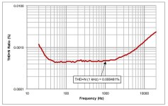
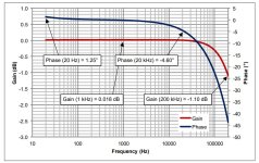
I disagree with your reasoning. If you add resistors to an input with a capacitance, you create an RC network, which has an effect on phase and frequency response. These effects are minimal with the active attenuator. Also included are the measured values of the active attenuator.If your happy with the active solution please stay with it.
Now you have changed a lot(fase and distorsion), but you like it.🙂
I think the best solution was a resistor devider done the right way.(change no fase, freq resp. and distorsion)
Attachments

Now the power amplifier is driven by a low impedance output and only a 1K resistor. Adding extra resistors can have an effect if the input acts not linear.
The volume potentiometer on the pre-amp circuit board is 50K, which probably means that it is connected directly to the input without a buffer. If a low pass filter and amplification is applied afterwards, attenuation could be made before that without LC circuit problems.
The volume potentiometer on the pre-amp circuit board is 50K, which probably means that it is connected directly to the input without a buffer. If a low pass filter and amplification is applied afterwards, attenuation could be made before that without LC circuit problems.
Usually an active attenuator / pre-amp outperforms passive. Some people don't want to believe this, but there are various reasons for this, mainly related to compromising on impedances and adding more serial resistance that raises noise levels.
The source may start distorting if too heavily loaded. The destination may start distorting if driven from a high impedance (non linear input current issue). The present situtation with audio signals is that output stages are typically 100 ohms impedance, and inputs 10k or 47k, but expect to be driven from much lower impedance (100 ohms). Using a passive potentiometer of say 47k will introduce upto 20nV/√Hz, whereas common active devices are more like 4 or 5nV/√Hz, and can work with pots of 10k or 5k (which are quieter). Another issue with higher value pots is the high impedance nodes are more susceptible to noise pickup, though good shielding practice should make this a non-issue.
Many amplifiers' specifications are assuming a low source impedance - amplifier input stages can have higher distortion with high source impedance than the datasheet will show - the input current and impedance is non-linear (feedback works to relate the output voltage to the input voltage, doesn't care about the input current.). And also input current noise (which usually can be ignored) will be boosted by high source impedance.
The standard Baxandall style volume control can amplify or attenuate, with no headroom loss, and is a no-brainer is most situations especially as it can use linear-taper pots. Its has the weakness that it inverts, but often a neighbouring stage can re-invert and restore correct phase.
Certainly a passive attenuator is a quick and simple solution, but it will struggle to reach the highest performance levels.
There's a less well known issue with log versus linear pots - the pot track resistance can be slightly non-linear (voltage coefficient of resistance), but in a linear pot the whole track is the same, meaning the ratio of resistances is linear (non-linearity cancels out). With a log taper the different sections of the pot have different electric-field strengths across them and this cancellation will be less precise. Not sure if this has ever been measured, but its a theoretical reason to both go with linear pots, and go with improved track materials (cermet rather than carbon?).
I finally decided to make an active attenuator with the low noise dual opamp OPA1612 and I'm going to place it between the preamp and power amplifier section. The 20 volt supply comes from the preamp section. The 20 volt I convert with the 2nd amp in the OPA1612 to a virtual ground. By adjusting the 20K input resistor you can make any attenuation needed.

The OPA1612 seems to be unable to deliver enough current. I also had to increase the capacity across the voltage divider. I am now going to try a circuit with a buffer LME 49600.
https://www.buildcircuit.com/hi-fi-stereo-headphone-amplifier-using-lme49600/
https://www.buildcircuit.com/hi-fi-stereo-headphone-amplifier-using-lme49600/
Today I was busy again with placing the signal attenuation in the Sugden itself. I wanted to attenuate between the pre- and power amplifier, but I discovered that with an input signal of 1.77 Vrms the pre-amplifier started to distort when the potentiometer was set to 2/3. The Meitner DAC even has 2.3 Vrms.
So the attenuation must take place at the input of the Sugden.
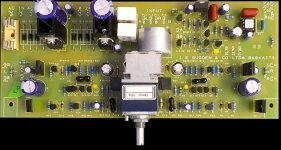
I looked at the input circuit in the Sugden and determined that the input is a 475 ohm resistor in series with the 50Kohm input potentiometer. Only after the potentiometer do I encounter an HF capacitance.
That means that I can place a resistor attenuator at the input of the pre-amplifier board without any problems. I chose 10.2Kohm in series and 475 ohm parallel. Seems to work fine. High frequencies such as 50KHz are also not attenuated. So with there resistance values I end up with a damping factor 22.5x. or -27dB.
now the potentiometer can be set to twelve o'clock and the sound is still beautiful.
So the attenuation must take place at the input of the Sugden.
I looked at the input circuit in the Sugden and determined that the input is a 475 ohm resistor in series with the 50Kohm input potentiometer. Only after the potentiometer do I encounter an HF capacitance.
That means that I can place a resistor attenuator at the input of the pre-amplifier board without any problems. I chose 10.2Kohm in series and 475 ohm parallel. Seems to work fine. High frequencies such as 50KHz are also not attenuated. So with there resistance values I end up with a damping factor 22.5x. or -27dB.
now the potentiometer can be set to twelve o'clock and the sound is still beautiful.
Attachments

I finally decided to make an active attenuator with the low noise dual opamp OPA1612 and I'm going to place it between the preamp and power amplifier section.
That is not an active attenuator, rather it is a passive attenuator with a buffer on the output.
This TI note has an example of an active attenuator.
https://e2e.ti.com/support/amplifie...0628/tle2072a-active-attenuator-output-spikes
- Home
- Source & Line
- Analog Line Level
- Active attenuator