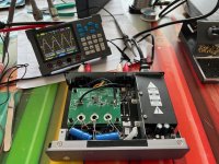
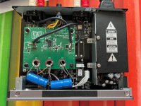
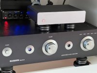
A common problem when connecting audio equipment is that the input and output levels are not matched. Equipment such as CD players, streamers and DACs nowadays have a high output voltage. Amplifiers on the other hand often have a gain that is much too high for these sources, which makes it almost impossible to turn up the volume knob. I ran into this problem when I connected my Meitner DAC with an output voltage of even 2.3 Volts to my Sugden A21SE. To solve this problem I did not want to use passiva attenuators, because I have experienced that they can negatively influence the sound, which has to do with the capacity and impedance of the amplifier input. However, an active attenuator does not exist, so I made something myself based on a design by TI called “Active Volume Control for Professional Audio”. The TI volume control has a super low noise and distortion and the output is buffered, so that the sound is not affected by this circuit. As a housing for the 2 TI Printboards I used a Cambridge Phono preamp, partially dismantled it and mainly used the internal dual 15 volt power supply and the output relay with control. I needed a attenuation of about 28dB to get it right!!! Vin/Vout=25!!!
Attachments
Last edited:
Hi, the problem is not common (except for the tube world) as the 2V rms line level standard and 0.5 .. 1V input sensitivity of power amplifiers are thankfully both pretty normal.
In this case it is really the Sugden that is to blame with its absurd 110 mV input sensitivity for full output. It is known for it as it annoys quite some owners. It would be nice to know how the input section is designed, probably a small change in the Sugden can make it up to standard without penalty.
In this case it is really the Sugden that is to blame with its absurd 110 mV input sensitivity for full output. It is known for it as it annoys quite some owners. It would be nice to know how the input section is designed, probably a small change in the Sugden can make it up to standard without penalty.
Last edited:

Insert line level attenuator into the input which is too hot.A common problem when connecting audio equipment is that the input and output levels are not matched. Equipment such as CD players, streamers and DACs nowadays have a high output voltage. Amplifiers on the other hand often have a gain that is much too high for these sources, which makes it almost impossible to turn up the volume knob. I ran into this problem when I connected my Meitner DAC with an output voltage of even 2.3 Volts to my Sugden A21SE. To solve this problem I did not want to use passiva attenuators, because I have experienced that they can negatively influence the sound, which has to do with the capacity and impedance of the amplifier input. However, an active attenuator does not exist, so I made something myself based on a design by TI called “Active Volume Control for Professional Audio”. The TI volume control has a super low noise and distortion and the output is buffered, so that the sound is not affected by this circuit. As a housing for the 2 TI Printboards I used a Cambridge Phono preamp, partially dismantled it and mainly used the internal dual 15 volt power supply and the output relay with control. I needed a attenuation of about 28dB to get it right!!! Vin/Vout=25!!!
https://www.parts-express.com/Harrison-Labs-12-dB-RCA-Line-Level-Attenuator-Pair-266-244
@adison, passive attenuators are made of resisitors and they influence the sound. Above that I needed -28dB!
Best is a low impedance signal to drive an input.
Best is a low impedance signal to drive an input.
It seems you are pretty sensitive to sound quality and ways to preserve it/not affect it (the sound) while being able to fine-tune the overall gain. So here's the schematic diagram that should resemble your amp pretty closely. Use the trim pot in place of the 470k resistor, and then find the suitable gain. Then measure the trimpot resistance and insert the corresponding discrete resistor value. This would be easier than going inside that CD player of yours to adjust the gain of its output stage.
You could also just go ahead with a 390k resistor if the trimpot is too much of a hassle - that should be okay for your needs.... but the trimpot would most accurately get you the desired sweet spot.

Edit: or just solder a resistor on top of that 470k to get to 390k...
You could also just go ahead with a 390k resistor if the trimpot is too much of a hassle - that should be okay for your needs.... but the trimpot would most accurately get you the desired sweet spot.
Edit: or just solder a resistor on top of that 470k to get to 390k...
Last edited:
2 resistors affect negatively the sound but a complex active device plus lots of attenuation does not? Sure.
The volume control in that A21Se is as passive and resistive (and cheap!) as can be so the reasoning is off. The real solution is to have the Sugden adapted to the world not vice versa (or by adding stuff in between).
It simply makes no sense to correct A21SE its too high GAIN by attenuation of sources standard line levels and then amplifying again. Correcting an error with an error that is. Practically every device bought today will not have a nice relationship with A21SE. Amplifiers in general do not have too high gain, this amplifier has too high gain.
It simply makes no sense to correct A21SE its too high GAIN by attenuation of sources standard line levels and then amplifying again. Correcting an error with an error that is. Practically every device bought today will not have a nice relationship with A21SE. Amplifiers in general do not have too high gain, this amplifier has too high gain.
Last edited:
Active devices commint lot more crime than simple resistors. Read no active device is linear. Resistors are. But suit yourself.@adison, passive attenuators are made of resisitors and they influence the sound. Above that I needed -28dB!
Best is a low impedance signal to drive an input.
Above that, passive attenuator are just two resistors, you can design any -dB.
It seems to me passive attenuator followed by clean buffer (b1) would be the most transparent solution.
It seems to me passive attenuator followed by clean buffer (b1) would be the most transparent solution.
This looks like the best sollution. I soon will have a look inside the Sugden.It seems you are pretty sensitive to sound quality and ways to preserve it/not affect it (the sound) while being able to fine-tune the overall gain. So here's the schematic diagram that should resemble your amp pretty closely. Use the trim pot in place of the 470k resistor, and then find the suitable gain. Then measure the trimpot resistance and insert the corresponding discrete resistor value. This would be easier than going inside that CD player of yours to adjust the gain of its output stage.
You could also just go ahead with a 390k resistor if the trimpot is too much of a hassle - that should be okay for your needs.... but the trimpot would most accurately get you the desired sweet spot.
View attachment 1439481
Edit: or just solder a resistor on top of that 470k to get to 390k...
I found pictures of the circuit boards of the amplifiers in the A21SE on the internet and you can clearly see that the components at the input correspond exactly with the diagram. The feedback resistor is actually 470K and can easily be adjusted by soldering a resistor in parallel. Then it is a matter of measuring and determining the correct value. I will start working on it next weekend.

Good. I'd also use only a single high quality reisistor in that position.
Dale metal film vs. Allen Bradley carbon film would be my choice, with one providing detail and extension, and the other making everything more mellow and warm but still quite detailed.
Dale metal film vs. Allen Bradley carbon film would be my choice, with one providing detail and extension, and the other making everything more mellow and warm but still quite detailed.
The greater the attenuation needed, the easier it is to design a transparent two resistor attenuator.@adison, passive attenuators are made of resisitors and they influence the sound. Above that I needed -28dB!
Best is a low impedance signal to drive an input.
The input resistance naturally becomes higher and the output impedance lower.
I would start with something like: 24k and 1k gives 28 dB.
Low attenuation values are more likely to be bad compromises.
I’m gonne change the feedback resistor in de amp itself. That’s the best solution.
I doubt. Sugden replies: Our amplifies are designed with high gain as this gives the sound we prefer on our products. Making the change you are suggesting is not something we would recommend
They are in their own world with regards to gain (it is design poverty). Nobody likes volume to be very loud at 1 o'clock or distortion but Sugden dictates the way they see it and that would not be an issue if they would produce fitting 200 mV sources which they don't except 1 DAC. A DAC that has....2.15V rms output level. That is why they are a British cottage industry brand.
What can be is that the feedback loop needs other changes. Many amplifier experts here that can tell.
What can be is that the feedback loop needs other changes. Many amplifier experts here that can tell.
Last edited:
Just to clarify, if it's attenuation (-28dB) then it's Vout/Vin. Vout=0.092V if Vin=2.3V...I needed a attenuation of about 28dB to get it right!!! Vin/Vout=25!!!
- Home
- Source & Line
- Analog Line Level
- Active attenuator