Hi Bones,
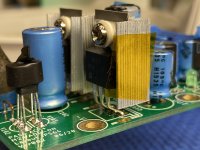
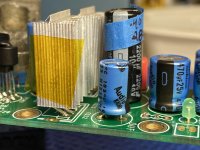
C111 can be reduced from 3300uF in size to give more room for HS clearance. Bend the Mosfet legs to move them forward. I found these tweaks to help a lot.
C111 can be reduced from 3300uF in size to give more room for HS clearance. Bend the Mosfet legs to move them forward. I found these tweaks to help a lot.
Attachments
Thanks for that. It’s a good fallback position.I have the standard Nichicon caps in place. I’ll try some of the heat sinks that I have ordered, and decide if I want to downsize caps, and bend legs. Now, if someone, in Europe, were to get some of the specified heat sinks ordered for a group buy...
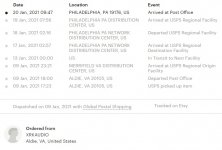
I still have not received mine.
Sorry about that, I think you are experiencing the Eastern Seaboard USPS delays that I experienced.
I still have not received mine.
Ditto
Attachments
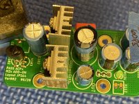
I got some smaller heatsinks with a 32 thermal resistance (vs the 24 of the specified Fischer heat sinks)
Will these be enough for the new lower bias setting? Or do I need to find some with a rating closer to 24?
Will these be enough for the new lower bias setting? Or do I need to find some with a rating closer to 24?
The née lower bias is very helpful to get the heat down. Give it a try and see what the temp is.
I plan to. I got the power bypass caps with the correct pitch for the Hakuin cards too. Next soldering session I get, I’ll finish Hakuin, and mount the output transistors on the ACP+, and try to figure out the final resistor with lab PSU, and potentiometer. I’ll try to remember to shoot temps.
Finished the Hakuin boards (all the possible SMT parts used) and the ACP+ boards. I did not have time to tap the PSU of one of the M2x units to power the ACP+ boards to work on the bias resistor before we headed off to the beach for the weekend. I will get there. Thanks XRK!
Small condo in a small town on the Florida Panhandle. Weather is going to be in the low 60s this afternoon when I go for my walk. We come about 2 weekends a month. My wife loves the beach, I like the 2 days away.
But yes, life is good. It was so crowded this year with all the parents/kids doing remote work/school.
But yes, life is good. It was so crowded this year with all the parents/kids doing remote work/school.

Hoping to cobble a +/- 24v PSU to try and figure out a bias number this weekend.
I currently have working versions of the PCA and Hakuin boards. All sounding great!
I currently have working versions of the PCA and Hakuin boards. All sounding great!
Last edited:
Getting that bias current through the JFETs set to the correct value helps to make it sound great. It’s not that hard if you use a trimpot and then swap to a fixed value resistor.
For us M2X users, I would appreciate any tips on how the overall gain of this ACP board can be adjusted.I think, as designed, it’s probably +9dB. I would like +5dB.
Any advice?
I also have the same question for the PCA and Hakuin boards. The WBA18 and Melbourne gain setting adjustments have already been documented in their respective threads.
Thanks,
Anand.
Any advice?
I also have the same question for the PCA and Hakuin boards. The WBA18 and Melbourne gain setting adjustments have already been documented in their respective threads.
Thanks,
Anand.
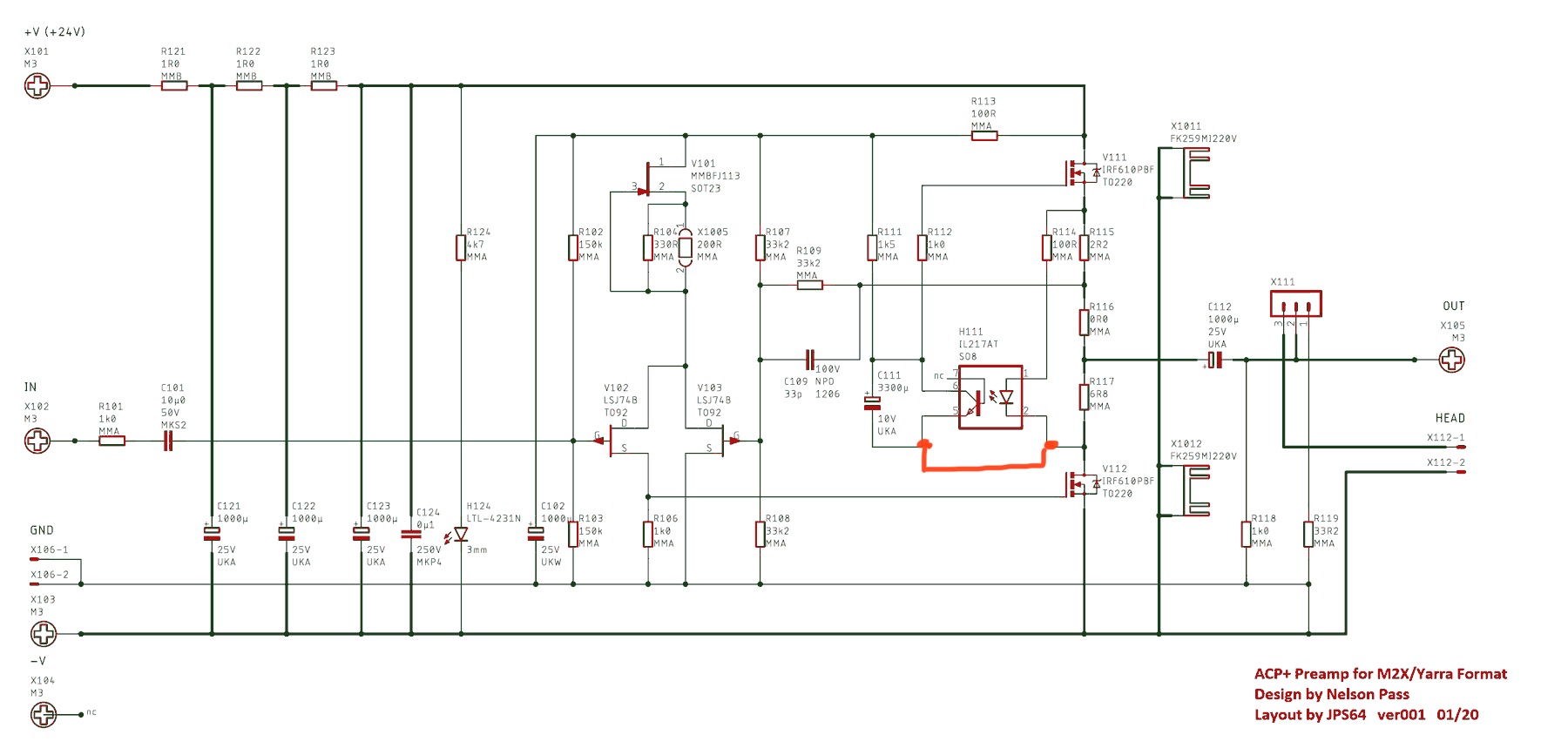
The feedback resistor R109 is between the output and the second JFET on the LTP.
This is a Pass circuit so maybe you would be better off getting an answer from the ACP+ thread in the Pass forum? If I were to offer any changes to the gain, I can’t guarantee it will be stable.
Typically making feedback resistor smaller in value will lower gain...
This is a Pass circuit so maybe you would be better off getting an answer from the ACP+ thread in the Pass forum? If I were to offer any changes to the gain, I can’t guarantee it will be stable.
Typically making feedback resistor smaller in value will lower gain...
Last edited:
Hello,
I noticed that Vunce jumpered C101. Is that the recommendation if using the Yarra motherboard?
I also noticed Vunce jumped something else with a little red jumper. Was that necessary only on the prototype board or is that something we need to pay attention to?
Edit, as well is X111 only needed if wanting a headphone output?
Thanks,
Alan
Last edited:
X111 should be jumpered 1-2 for headphones out. But if using as preamp, jumper 2-3 to give it a 32ohm load. The circuit ideally likes to be loaded to give the correct harmonic profile. But if you reduce the bias current, increase the on board load resistor accordingly. Probably 100ohm is fine for general use
Vunce bypassed C101 as the Yarra main board provided the cap coupling. Be careful when using the ACP+ elsewhere where there might not be cap coupled input.
Vunce bypassed C101 as the Yarra main board provided the cap coupling. Be careful when using the ACP+ elsewhere where there might not be cap coupled input.
Finally started soldering on my Yarra boards last night. It's only been how many years?!? So I'm planning on building up the Haikun and ACP+ boards. H111, the phototransistor, is out of stock on Mouser. A few potential substitutes appear to be 782-IL1208AT and 782-IL212AT. Specs appear very similar with the exception of the Current Transfer Ratio. The original spec'd part has a CRT of 130%. The other parts I found are 80% and 320% respectively. Any thoughts on how these might perform in the circuit? I'm afraid that 80% won't be enough or 320% would be too much.
- Home
- Group Buys
- ACP+ Preamp/HPA for Yarra Preamp