Hi Mark
I am not sure that a 24 dB/oct Linkwitz/Riley complementary filter can do a square-wave!
You're correct, it can't.
The slope af a Duelund 24dB LP on the woofer in a three-way system is different from a 24 dB/oct Linkwitz/Riley-slope!?
Which side of the woofer do you mean? I assume the top end of response where it crosses to the mids, because low end is immaterial to how square waves are produced up above the low end rolloff; and, as all low end roll-offs, no matter the speaker in question, will have a similar effect on square waves down in the roll-off region.
I do not know the Dueland crossover per se, it looks very similar to what folks here call a Harsch.
I don't think any of that matters though.
The only thing that matters with reproduction of square waves is ...(take 3 guesses, first two don't count Lol).......good ole flat mag, and flat zero phase .
It's that stinkin simple...anything short of that, anything that has phase rotation no matter how flat freq response is, will wonk out square waves.
I'd love for someone wiser than me to show it otherwise..........
Me too, my IIR filter knowledge is soooooo low, (and i plan on keeping it that way 😉)But again my filter-knowledge is limited and I dont won´t to be argumentativ without being sure I am right. 🙂
Don't forget to try the Alignment tool in REW. This is much simpler than trying to align impulses manually and you can visually see the two traces, how they match in phase and magnitude. There is also an auto align feature where you choose the crossover point and REW will vary the delay to align the phases at that point.When I align the beginning of the impulses, I actually get that there should be a delay of 0.02 ms on the MF. So what is actually correct? I guess the phase will tell? I am getting really close - all the things start clicking together for me now.
Graphs in this post here to demonstrate
https://www.diyaudio.com/community/...hase-matching-using-a-dsp.361207/post-6387357
Hi Mark
I do not think so, and it was developed long before the Harsch filters in the late eighties. Have a "recreational read" of the Duelund paper, you don´t need to understand the math really (I can´t follow that anymore 😉 )
This Duelund-paper is a bit special, in that Duelund states, that all the filters with names that we use, are not designed to sum phase-correctly as a whole system! He says the filters were developed for telephones (one-way!), not for audio!? The paper tells the story of the development of phase-coherent filters.
Steen Duelund starts from scratch to develop "audio-filters" for multi-way-systems by defining what he wants them to do, mathematically. Then he develops the differential equations (transferfunctions I guess) for two-way-systems and for three-way-systems ( he even took it to a four-way system later). The formulars provide target-curves (acoustic) for each way to follow, so that the whole system sums perfectly and in phase. Each filter-way is designed to have the exact same phase-response.
He "discovers" in the proces, that a second order Linkwitz/Riley-filter, LP on the woofer and inverted polarity on the HP for the tweeter in a two-way system follows his rules for a "perfect"filter, and produces a coherent summation!
Then he takes it further to a three-way-system, with taget-curves that are not resembling "normally known filters". He develops the transfer-functions for all three ways as a combined whole! He says, that you CAN NOT look at the crossover from woofer to mid isolated from the tweeter, they are all connected in his topology. They all need to have the exact same phase-curve. That results in the Target-curves shown in the paper. Well the details can be read there.....
I have read that paper many times, and this theory has been my "upbringing" in DIY-lodspeaker-building since the start nineties as I have been speaking to my old loudspeaker friend telling stories and explaining the practical implementation of the Duelund-filters. I have once met and visited Mr. Steen Duelund in Copenhagen, he was quite special, and his speakers were extremely good sounding.
I have been contemplating on how to implement Duelund-filter´s in MEH´s for a long time, but .........................
Well, I think I will stop here for now.
Steffen
I do not know the Dueland crossover per se, it looks very similar to what folks here call a Harsch.
I do not think so, and it was developed long before the Harsch filters in the late eighties. Have a "recreational read" of the Duelund paper, you don´t need to understand the math really (I can´t follow that anymore 😉 )
This Duelund-paper is a bit special, in that Duelund states, that all the filters with names that we use, are not designed to sum phase-correctly as a whole system! He says the filters were developed for telephones (one-way!), not for audio!? The paper tells the story of the development of phase-coherent filters.
Steen Duelund starts from scratch to develop "audio-filters" for multi-way-systems by defining what he wants them to do, mathematically. Then he develops the differential equations (transferfunctions I guess) for two-way-systems and for three-way-systems ( he even took it to a four-way system later). The formulars provide target-curves (acoustic) for each way to follow, so that the whole system sums perfectly and in phase. Each filter-way is designed to have the exact same phase-response.
He "discovers" in the proces, that a second order Linkwitz/Riley-filter, LP on the woofer and inverted polarity on the HP for the tweeter in a two-way system follows his rules for a "perfect"filter, and produces a coherent summation!
Then he takes it further to a three-way-system, with taget-curves that are not resembling "normally known filters". He develops the transfer-functions for all three ways as a combined whole! He says, that you CAN NOT look at the crossover from woofer to mid isolated from the tweeter, they are all connected in his topology. They all need to have the exact same phase-curve. That results in the Target-curves shown in the paper. Well the details can be read there.....
I have read that paper many times, and this theory has been my "upbringing" in DIY-lodspeaker-building since the start nineties as I have been speaking to my old loudspeaker friend telling stories and explaining the practical implementation of the Duelund-filters. I have once met and visited Mr. Steen Duelund in Copenhagen, he was quite special, and his speakers were extremely good sounding.
I have been contemplating on how to implement Duelund-filter´s in MEH´s for a long time, but .........................
Well, I think I will stop here for now.
Steffen

Hej Steffen
Like Duelund I am also using crossovers that have only one 360° phase turn over the whole working range. While such a filter can be designed such that its group-delay distortion is much lower than that of a Linkwitrz Riley it will never reproduce a square wave correctly - neither will a Duelund crossover.
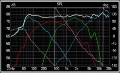
IIRC TD once said that his MEHs could reproduce a reasonbably accurate square-wave. I therefore wonder whether the shown phase-measurement is really correct because this one wouldn't allow the reproduction of a square wave. (but it is indeed almost linear phase from about 100 Hz to 2.5 kHz approx !!!).
Regards
Charles
Like Duelund I am also using crossovers that have only one 360° phase turn over the whole working range. While such a filter can be designed such that its group-delay distortion is much lower than that of a Linkwitrz Riley it will never reproduce a square wave correctly - neither will a Duelund crossover.
IIRC TD once said that his MEHs could reproduce a reasonbably accurate square-wave. I therefore wonder whether the shown phase-measurement is really correct because this one wouldn't allow the reproduction of a square wave. (but it is indeed almost linear phase from about 100 Hz to 2.5 kHz approx !!!).
Regards
Charles
I think the modern approach with active DSP crossovers is completely different than what Duelund and other folks have done in the past. The mathematical approach works only with a lot of assumptions that do not fit reality. Look simply at the substitute circuit diagram for a speaker here:

Sorry for posting with German, i did not find any other picture real quick.
If you try to take all things into account the transfer function of the electrical filter and the speaker together is so complex that it get nearly impossible to calculate.
The modern approach is to automate the process of the large number of iterations to find the best settings with try and error. This is what room correction software can do, manually it will take a lifetime of listening tests to do this.
Some folks are better than other to implement a system intelligent enough for this kind of approach, from what i have heard these guys know really what they are doing, but the devices are not really cheap...
ABOUT TRINNOV
I have no money for such an intelligent correction system and take the time to do the iterations manually with a reference system on my desk with a nearfield monitor subwoofer plus satellites setup with Genelec speakers that are known to sound very clean for sound engineering purposes.
Last edited by a moderator:
The circuit that you show is only third order which is still manageable with maths. I go a middle route: I use DSP to prototype analog active crossovers which is quite conventient. A little attention has to be paid to the fact that IIR filters are not an exact replica of analog active filters. The closer you go to the Nyqvist frequency the more you have to take care of that.
Regards
Charles
Regards
Charles
Duelund (3way) topology is nice and what I like to get - and rather easy with dsp . Basically elliptic acoustic responses and woofer and tweeter should sum well too, that's the point. Mid fills in that gap and sums with woofer and tweeter, with inverted polarity. It sounds better to me than all-LR4, which has more excess group delay.


Hi Mark
I do not think so, and it was developed long before the Harsch filters in the late eighties. Have a "recreational read" of the Duelund paper, you don´t need to understand the math really (I can´t follow that anymore 😉 )
Hi Steffen, yes i see the difference now. Thanks!
And a quick take away for me is Harsch is really for a two-way, as opposed Dueland a 3-way.
Like i said, when it comes to xovers....i REALLY want nothing to do with IIR Lol
Yes, once past a 2-way, a Linkwitz/Riley does not hold up without cascading filters and adding all-passes.He "discovers" in the proces, that a second order Linkwitz/Riley-filter, LP on the woofer and inverted polarity on the HP for the tweeter in a two-way system follows his rules for a "perfect"filter, and produces a coherent summation!
Then he takes it further to a three-way-system, with taget-curves that are not resembling "normally known filters". He develops the transfer-functions for all three ways as a combined whole! He says, that you CAN NOT look at the crossover from woofer to mid isolated from the tweeter, they are all connected in his topology. They all need to have the exact same phase-curve. That results in the Target-curves shown in the paper. Well the details can be read there.....
I think doing that fully mitigates the issues Dueland found with his 3-way
Linkwitz describes the needed setup: https://www.linkwitzlab.com/frontiers_5.htm#V
I've built that setup for 4-ways and it did provide complementary electrical summation across the entire combined transfer function.
Hi Mark
Year, the more I try to figure out how to do things in IIR, it seems like a hard road to travel!? I will see, I have MiniDSP hardware to go both routes up to a four-way system. Last week I watched some you-tube videos with Mitch Barnett describing what he can do with FIR. Hmm, sounds tempting!
Like i said, when it comes to xovers....i REALLY want nothing to do with IIR Lol
Year, the more I try to figure out how to do things in IIR, it seems like a hard road to travel!? I will see, I have MiniDSP hardware to go both routes up to a four-way system. Last week I watched some you-tube videos with Mitch Barnett describing what he can do with FIR. Hmm, sounds tempting!
Hi Mark!Linkwitz describes the needed setup: https://www.linkwitzlab.com/frontiers_5.htm#V
Interesting! I see point 5, that there are Crossover topology issues with 4-way systems in L-R.
Is this because the phase rotates 360 plus a little more?
I am planning to add a midbas to my system (using a digital filter) and have simulated the result, is this a bad idea?
I see no radical problems in my simulation. Any thought?
LR12:
Attachments
Still not getting the full picture, but I got some "aha" moments while reading the linked article by Siegfried Linkwitz and what he linked there. The 4 way topology there makes sense and it looks like a good way forward after I get my first 2 way crossover perfected.
A Symetrix Cobra 8x8 is on its way to me and there I can play around with IIR filters in am unlimited way. FIR capacity is unfortunately a bit limited, so more ambitious FIR experiments will be done via CamillaDSP later.
A Symetrix Cobra 8x8 is on its way to me and there I can play around with IIR filters in am unlimited way. FIR capacity is unfortunately a bit limited, so more ambitious FIR experiments will be done via CamillaDSP later.
Hi Viper_user,Hi Mark!
Interesting! I see point 5, that there are Crossover topology issues with 4-way systems in L-R.
Is this because the phase rotates 360 plus a little more?
I am planning to add a midbas to my system (using a digital filter) and have simulated the result, is this a bad idea?
I see no radical problems in my simulation. Any thought?
The topology issues come from multiple filters overhang into the same freq range.
Iow, the xover regions have more than two players involved. This occusr with both phase rotation and magnitude.
You can see the dip in mag from 4th order LRs at 300Hz and 1 kHz here:

If you were to spread the xover points out further, to say 300Hz and 3 kHz, you wouldn't see the dip in mag.
But in a 4-way, i guess it's about impossible to spread them all out so there's no overlap.
I'm really not the right guy to ask about IIR xovers...others who have posted in this thread are way more knowledgeable about them....and I HATE them haha.
As far as adding a midbass....if more ways can be successfully put together, my vote is yes.
So far with my 5-ways i am seeing/hearing nothing but benefits (apart from cost and complexity)
Mark, i think i can notice some of this effect between 850hz and 4300khz in my current 3way setup. Maybe i should study some FIR software to add.
https://www.minidsp.com/applications/advanced-tools/rephase-fir-tool
In pro audio for live music, i have never heard of this problem, they use 4way and just hook them LR4's up, and flip.
https://www.minidsp.com/applications/advanced-tools/rephase-fir-tool
In pro audio for live music, i have never heard of this problem, they use 4way and just hook them LR4's up, and flip.
Last edited:
Post #70 is worth trying, I used to listen to that just fine. Just takes some time to get right in acostic measurements indoors, below 4-500Hz all sorts of reflections and modes are messing it all. Outdoor ground plane would be nice, if weather etc. permit.
I real life, theroretical/simulated "problems" often get coverd with others... With dsp this kind of tests are actually fun and educative! It costs only time.
I real life, theroretical/simulated "problems" often get coverd with others... With dsp this kind of tests are actually fun and educative! It costs only time.
Maybe I am overlooking something, but I don't really see why that is so different than an all LR2 3-way crossover. According to the step response, tweeter comes first, with negative polarity, then midrange with positive polarity, lastly the woofer (probably swamped by room acoustics to produce clean step at the mic) with negative polarity , same as an all LR2 3-way.Duelund (3way) topology is nice and what I like to get - and rather easy with dsp . Basically elliptic acoustic responses and woofer and tweeter should sum well too, that's the point. Mid fills in that gap and sums with woofer and tweeter, with inverted polarity. It sounds better to me than all-LR4, which has more excess group delay.
View attachment 1028745View attachment 1028746View attachment 1028747
Maybe not but you posted the right link where Linkwitz explained it above.You can see the dip in mag from 4th order LRs at 300Hz and 1 kHz here:
I'm really not the right guy to ask about IIR xovers...
In the 300Hz and 1K case a level increase on the mid would fix most of it at least in real life where things are not as flat. If that is not enough an all pass filter of the right type has the same effect as the cascading does on the phase response.
Raise the level of the red driver and drop the level of the green in some combination and most of the difference will go away.Mark, i think i can notice some of this effect between 850hz and 4300khz in my current 3way setup.
If you see the scale in Linkwitz's graph the residual ripple after level correction is less than 1dB, not a major issue in a live setup.In pro audio for live music, i have never heard of this problem, they use 4way and just hook them LR4's up, and flip.
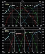
I compared my simulation in vituix and one can see that 24db would benifit from FIR.
it would be interresting to flip between flat phase preset and standard LR24, but one has to take into account that it takes 8sec to load the memory, maybe too long to hear audiophile differences.
it would be interresting to flip between flat phase preset and standard LR24, but one has to take into account that it takes 8sec to load the memory, maybe too long to hear audiophile differences.
Attachments
Last edited:
There is a lot that could be altered with level and EQ regardless of IIR or FIR.I compared my simulation in vituix and one can see that 24db would benifit from FIR.
It is easy enough to remove the phase turn from the crossovers with rephase and use that filter to convolve with some music samples and make yourself an ABX test of the difference.it would be interresting to flip between flat phase preset and standard LR24, but one has to take into account that it takes 8sec to load the memory, maybe too long to hear audiophile differences.
it would be interresting to flip between flat phase preset and standard LR24, but one has to take into account that it takes 8sec to load the memory, maybe too long to hear audiophile differences.
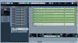
Hi,
You've got a daw. So process files offline ( destructive, you work on the audio not some real time processing): then you create two groups and use solo and/or mute to shift from one to another. No delay.
The differences are sometimes subtle but they are here between FIR and IIR. For monitoring real time i find latency of FIR to be a real issue with some musicians... so i've got an IIR and a FIR preset: when monitoring during takes i switch to IIR, when critical listening FIR.
Last edited:
Haha Krivi, i have done just that and forgot it, it was a test with filtered vs full. I have now re opened and listen, i can solo on selection and got instant AB test, and well, it's m i n i m a l! (the sound is a little bit more tame in the filtered sum) but this is on 3way. May do a 4way some day also where it will be more present.
In fact 4way 12db looks better than 3way 24db concerning phase in wituix.
So why sound FIR better than IIR? its just digital and doing the same thing?
In fact 4way 12db looks better than 3way 24db concerning phase in wituix.
So why sound FIR better than IIR? its just digital and doing the same thing?
Attachments
Last edited:
- Home
- Loudspeakers
- Multi-Way
- Acoustic versus electric crossover slope - how to design properly using DSP? Please advise...