Damn - I started my print yesterday - 92% done on the base.
Since you are still making tweaks, any way to include alignment pins for the petals? Maybe something as simple as a couple of 1.8mm holes (so one can use pieces of filament to align)?
Since you are still making tweaks, any way to include alignment pins for the petals? Maybe something as simple as a couple of 1.8mm holes (so one can use pieces of filament to align)?
Also - I'm printing the "lock" version. Is there any tolerance allowed with the lock? I'm not sure whether I'll be able to print and glue the petal 100% precisely so that they still allow the male/female part of the lock to function properly and allow the petal to sit flat on the base.I've added a version of the mounting flange specifically designed for the DFM-2535 (as it may be the only driver working with the horn in the end 🙂)
https://at-horns.eu/ext/athex/ATHEX-400-3625-STL-1.zip
View attachment 1206764
I just noticed the formula for Y was wrong in the post with the TAN referencing the angle along the ellipse instead of the skew angle. It should be:Hi Marcel,
Been following this thread for a while and your work has been amazing. One of the things that has stuck in my head for a while is wondering if there was a more continuous way to handle the round over than the SE. I threw a quick formula into excel using an ellipse rather than a skew line to define the OS profile and ended up with a result pretty close to one of your K=1 curves (attached alone and overlayed on your K=1 curve from a pdf on your website)
The basic thought was that for a pure OS, you have a a line rotated off parallel from the axis by some skew angle that gets swept around said axis. That line could also defined as a segment of a circle with infinite radius. If we make the radius of that circle finite, you start to get profiles that naturally terminate. My first attempt at a skewed circular sweep profile led to some extremely wide round overs, so I tried using an ellipse instead.
The formula from the spread sheet was Y =SQRT((Rthroat+(Rmouth-Rmouth*COS(aE))/eE)^2+(xE*TAN(aE))^2)
Where:
Rthroat = Throat radius (12.7mm)
Rmouth = Mouth radius (130mm)
aE = angle along defining ellipse (from 0-120 deg in this example)
eE = elongation of ellipse (1.73 in this example)
xE = axial distance at aE = =Rmouth*SIN(aE))*COS(aS)
aS = Skew angle or waveguide angle (39 deg)
I wish I could also supply some AKABAK results, but sadly I keep getting zero size errors and can't seem to get things running. I was interested in this family of profiles because it seems like plug molds could be produced with an ellipse cutting jig offset above a lazy susan
View attachment 1200835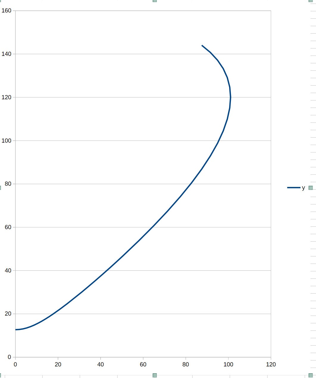
Y =SQRT((Rthroat+(Rmouth-Rmouth*COS(aE))/eE)^2+(xE*TAN(aS))^2)
I've updated the STL zip file, check for an added PETAL file ("LOCK-2").Since you are still making tweaks, any way to include alignment pins for the petals?
It will almost certainly require some cleaning/sanding to fit precisely, especially of the BASE part. This depends a lot on printing conditions and it's just not possible to account for that in advance for all cases. I included the "FLAT" versions as well, so everyone can choose their approach.Also - I'm printing the "lock" version. Is there any tolerance allowed with the lock? I'm not sure whether I'll be able to print and glue the petal 100% precisely so that they still allow the male/female part of the lock to function properly and allow the petal to sit flat on the base.
- I use 0.6mm nozzle (highly recommended for such prints), it will be different for 0.4 or anything else...
Last edited:

Wow- those are some really clean prints - five petals at the same time! I currently only have a .4 nozzle. Can I ask about the print settings? Layer height / wall thickness/infill type and density / top-bottom layer thickness
- I knew it would come handy some day! 🙂 The P.Audio PA-D99 2" 14kg monster, here with a simple conical adapter from the phase plug end to the 1.4" throat opening of the ATHEX 460-36.


The measurement is only rudimentary, not completely anechoic, but I would consider this already usable with a DSP (quite more than that, actually).

The measurement is only rudimentary, not completely anechoic, but I would consider this already usable with a DSP (quite more than that, actually).
Last edited:
0.6 mm nozzleWow- those are some really clean prints - five petals at the same time! I currently only have a .4 nozzle. Can I ask about the print settings? Layer height / wall thickness/infill type and density / top-bottom layer thickness
0.24 mm layer height
80 mm/s; 1500mm/s^2
2 perimeters, 3 top/bottom layers
10% cubic infill (25% for the base)
I could do 6 petals at once but I already had the first one printed separately. This took 19.5 hours.
Hi all, I've been trying to design an OS-SE waveguide and am using a paper I found on at-horns.eu. It mentioned a software called Ath which I could analyse the acoustic properties of the waveguide. Went to the website and it says the program is no longer available. Does anyone know where else I could get it from (maybe an older version) or an alternative? Cheers
Marcel can you please make harmonics spectra? (and post arta files)
I added links to the website so you can still download the tool and use it.Went to the website and it says the program is no longer available.
Wow - that's amazing speed. I'm very new to 3D printing. I have the very basic ender3.0.6 mm nozzle
0.24 mm layer height
80 mm/s; 1500mm/s^2
2 perimeters, 3 top/bottom layers
10% cubic infill (25% for the base)
I could do 6 petals at once but I already had the first one printed separately. This took 19.5 hours.
I.\'m assuming 80mm/s = print speed. What does 1500mm/s^2 refer to?
Have never messed with print speeds. Maybe worth a shot. As currently set up, I'm expecting 27 hours for two petals.
When you print at that speed, do you have to increase nozzle temp as well? I'm currently using 210 celcius for the nozzle, and 65 celsius for the bed.
Last edited:
That's the maximal acceleration. As the nozzle typically (de)accelerates most of the time, this can affect the total print time even more than the (maximum) speed alone, as it's not always even reached. It's good to find your maximum that still gives good quality prints.What does 1500mm/s^2 refer to?
Thank you, much appreciated.I added links to the website so you can still download the tool and use it.
This is stupid.
I wondered why it was not possible to avoid a waistband effect for horizontal polars. The waveguide would be 26 cm wide, the enclosure 31 cm:


The problem did not occur with the even shorter vertical opening. And indeed the issue is not in the waveguide, but the enclosure dimension:


I wondered why it was not possible to avoid a waistband effect for horizontal polars. The waveguide would be 26 cm wide, the enclosure 31 cm:
The problem did not occur with the even shorter vertical opening. And indeed the issue is not in the waveguide, but the enclosure dimension:
Last edited:
Edge diffraction 😉 Other way to reduce waistbanding due to edge diffration is to make the waveguide narrower coverage so that DI of the "waistband" matches to that of the waveguide.
You would have to try, I'm afraid, I'm not aware of anyone trying it befor
Since I'm only interested to use this down to 1100-1200 Hz, could anybody say if that would work with Peerless DFM-2544R00?
- Home
- Loudspeakers
- Multi-Way
- Acoustic Horn Design – The Easy Way (Ath4)