Ok, Where you see a peak and or dip in the frequency response. At least once I have asked you for SPL/Impedance/Phase all in one graph. These three together will tell you many things about a driver's operation. When you have a peak you generally have a resonance. And that can also be a resonance or anti-resonance (Adding or subtracting to the test signal) in the diaphragm or suspension. You will see these generally as fair narrow dips and peaks in a SPL graph. Every driver has this. I am not picking on compression drivers. When you design these you work to move them out of the passband you desire or minimize them as much as possible through a few different methods, dampening can have a little effect. Edge of diaphragm and surround junction is a major place to investigate, and thickness of the surround and where you make thickness changes.I still don't understand what you are looking for, on top of these graphs:
What I generally look at are un-smoothed graphs. In all three areas of measurement. They tell you much more. Pretty is for people that do not know what raw responses look like. They are ugly because they are magnified. An octave have 12 notes. 1/48th octave resolution is splitting that into 4 regions per note. Choice of mathematics in the FFT calculation will also make for either a finer resolution or a smoother coverup of the peaks and dips. On the end of the audio world that I work in I am interested in peaks and dips. They are the ones that make something terrible to listen to and drive you crazy if they are between 1 to 4k or 6 and 10k.
So a peak that shows up in an SPL response should ideally have a peak in the phase and in the Impedance. The delay between these is allowing you to understand the source and nature of the peak. Do you see it at a multiple of the first peak? Does it lessen in amplitude or grow? If it grows you have a sub-harmonic, the main harmonic will be the strongest one. If you see it in the impedance you have a motor, damper issue as well usually, but not always. Knowing the drivers dimensions, the surround dimensions and the frame dimensions and doing simple wavelength calculations will allow you to look for these areas to begin with. Full wavelength half wavelength are principal areas of trouble for reflections. But there can even be trouble at 1/4 wavelength when there are reflective structures like in a compression driver.
I hope I have answered some of the question. A little tired today!

Sure, peaks and dips. But there are virtually no peaks and dips in the presented data, that's the whole point. And as it's all minimum-phase (as has been verified numerous times), this implies that also the time behaviour is as clean as it can be. This is all seen from the polar data, even if amplitude only. We are not developing drivers or trying to examine problematic ones. We have good drivers measured in good horns... 🙂
I will post a raw impulse response later, I just don't save them at this point, so I will need to take some more measurements. I already posted one for some other design (not so clean as the latest additions): https://www.diyaudio.com/community/...-design-the-easy-way-ath4.338806/post-7431530 - that was the DFM-2535 as well.

Last edited:
BTW, when I designed the hexagonal horns (from which is the posted IR above), I hoped a bit they can also have an acoustic advantage in not being completely symmetric (which is generally considered a good thing), but that didn't turn out to be the case. The round Gen2 horns are still better and still the best I've seen. If there's any positive effect of the non symmetry, it's not as strong as the negative effects. The round shape is definitely not a problem, in fact it's quite the opposite.
Surprisingly for the DFM-2544R00 the datasheet I found says Mms is 0.3g and for the smaller DFM-2535R00 it says 0.5g, but the 2535R00 has 2x the Bl.
The front chamber volume is likely larger for the 2544, and the compression ratio could be higher because of the larger diaphragm. I think both would increase the rate of HF drop-off.
https://arxiv.org/abs/2403.17963
On page 5 there's a handy visualization for a simplified model showing the FR for different chamber depths at different compression ratios.
Based on this generally for our interests it would seem desirable to have low compression ratio phase plugs.
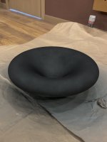
ATH E520G2 all glued up and ready for some painitng.
Whilst the included jig does a reasonable job of holding everything in place it doesn't really pull the petals down right into their seating as well as it could. Might I suggest a join that has registration pins and the ability to utilise fastners to pull the petals into the base. I was able to get precision prints (natural PETG) on my Voron and fit them with <0.5 gaps before glueing, however doing this with all the petals fitted and screwing the jig down requires way more arms than I have. 🙂 My joins are mostly <1mm however between petals and base some opened up to be larger than 1mm.
FYI natural PETG prints with a clear layer or 2 so the edges may look like a larger gap in the photo.
Nothing that a bit of filler couldnt fix though. 🙂
Glue used was a PU based one, hence the messy joins. For those doing it a first time make sure you tape all your joins with packing tape to prevent the jig sticking to the horn and make cleanup easier for the other joins. PU expands as it sets.
Printing settings:
- 0.2mm layer height, 0.4mm nozzle
- Natural PETG - prints the best and will show you EVERY blemish so it can be awesome for dialling in PETG.
- Scarf joins and put joins to the back, then rotate the part so the joins line up on the sharpest point of the curve on the back of the horn.
- 3-4 sidewalls/external layers with 10% bicubic infill. base was 20% infill.
- Printed slowly ( for a Voron) each petal was about 7 hours.
Hi, thanks sharing your printing tips! 7 hours per petal, thats 42 hours per waveguide + throat and possibly other parts. How much does it weight? Trying to get some idea of filament use. Thanks!
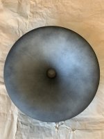
Here is mine, also from PETG. 0,1mm layer height and solid infill. No resonance probşems with the simple knock test. As I have always worked with wood and subtractive methods, this construction was one of the first for me. I liked how complex geometries can be printed but I did not like the finishing part. It takes time and involves chemicals I do not like that much!
I have already shared my glued and first layer of polyester putty filled photo before (https://www.diyaudio.com/community/...-design-the-easy-way-ath4.338806/post-7757232). Now, you can see full layer of primer and first and second layer of paint applied. I am not 100% happy with the results but this is my first try so I try to be easy on myself. Also, I will sand with very fine sand paper and apply another coat of paint yet. The thing is, it did not end up looking like a finished product (at least up to my standards). The cnc'ed wood takes much less time finishing and gives better results. I am hoping to build the same horn out of wood once I get the necessary files. The throat part can still be 3d printed, though I would prefer to get a mjf print for that.
I have already shared my glued and first layer of polyester putty filled photo before (https://www.diyaudio.com/community/...-design-the-easy-way-ath4.338806/post-7757232). Now, you can see full layer of primer and first and second layer of paint applied. I am not 100% happy with the results but this is my first try so I try to be easy on myself. Also, I will sand with very fine sand paper and apply another coat of paint yet. The thing is, it did not end up looking like a finished product (at least up to my standards). The cnc'ed wood takes much less time finishing and gives better results. I am hoping to build the same horn out of wood once I get the necessary files. The throat part can still be 3d printed, though I would prefer to get a mjf print for that.
Attachments
The whole waveguide and adapter / jig is almost exactly 2kg of petg.Hi, thanks sharing your printing tips! 7 hours per petal, thats 42 hours per waveguide + throat and possibly other parts. How much does it weight? Trying to get some idea of filament use. Thanks!
I second that. Slots and tabs (or slots in each part to insert a separate tab) would be better than pins, so that they allow some movement in one axis.Might I suggest a join that has registration pins and the ability to utilise fastners to pull the petals into the base.
I always do the petal assembly one by one, can't imagine doing it any other way. I first fasten the jig to the base and then insert petals, one at a time. The jig does push down but also outward so it's good to use a tape to prevent the petals from moving apart:
https://www.diyaudio.com/community/...-design-the-easy-way-ath4.338806/post-7643110
This way I find it really easy.
- Maybe instead of printing the waveguides, we could print molds. I've done that, it's also possible.
I agree that finising of the printed parts can be a pain. But this is DIY, after all, and 3D printers are way more accesible than CNC milling machines.
Last edited:
below is 2535 drawingBased on this drawing, does everyone agree that the exit angle of DFM-2535 is 22 deg?
(Which is right between the current STD-1 and STD-2 adapters.)
According to the technical drawing, the exit diameter at the phase plug is ~18.6 mm. Would be interesting to see if increasing directivity with a reducing insert works without messing up the FEA optimized response of the driver.

Group Buy: Peerless by Tympahny DFM-2535R00-08 (unobtanium extraordinary HiFi compression driver bulk order)
Group Buy: Peerless by Tympahny DFM-2535R00-08 (unobtanium extraordinary HiFi compression driver bulk order)
Last edited:
I tried a ring plug in the DFM-2535 with a smootly expanding adapter. These are unsmoothed frequency responses:

What seemed as a very smooth profile overall doesn't turn out that way. I think the expansion inside the phase plug is just as critial as anywhere else. Here it apparently doesn't match the rest. So, with the ring plugs it's also not that easy. The DFM-2535 is obviously optimized with the existing conical exit section.
But I can try some more rings, this was just a first try 🙂
But it still sounds fantastic. It can be well worth it, even if some additional EQ might be necessary.
I kind of expected this. Not the best outcome for a passive approach. If directivity is considerably better (lesser) in the high frequencies with a reducing insert, for those of us who use a DSP solution, it could still be interesting what a straight-walled ~18.6 mm insert does.
I am happy to announce we have reached a milestone today: one half of the drivers have found prospective buyers. There is 50 more.
Group Buy: Peerless by Tympahny DFM-2535R00-08 (unobtanium extraordinary HiFi compression driver bulk order)
I am happy to announce we have reached a milestone today: one half of the drivers have found prospective buyers. There is 50 more.
Group Buy: Peerless by Tympahny DFM-2535R00-08 (unobtanium extraordinary HiFi compression driver bulk order)
This is the second piece from my pair of DFM-2535s (in its original condition, including the bug screen and foam gasket, which doesn't allow the cleanest joint).
Attached is an on-axis impulse response in various formats, all exported from ARTA.
Anyone is welcome to analyze it and present any derived data, I don't have anyting to hide, I just don't think there's anything more to it than what has been shown.
For a reasonable CSD the available reflection-free time is quite limited (only 4.9 ms).
Attachments
Two a bit different ring plugs with the DFM-2535.
The top one is narrowing and then widening, the bottom one is more or less cylindrical. Both have in common that thay restrict the expansion at the exit of the driver. (I would expect a bigger difference.)


I wish we could model this...
The top one is narrowing and then widening, the bottom one is more or less cylindrical. Both have in common that thay restrict the expansion at the exit of the driver. (I would expect a bigger difference.)
I wish we could model this...
[/QUOTE]
Which 'time-frequency resolution' setting was used for your burst decay graphs? 1/3 or 1/6 octave resolution? I often find it irritatingly difficult to reproduce graphs with the same values in a different analyzer (REW vs ARTA in this case).

The 1" Peerless measured with the STD-3 adapter, on axis. That's all I can handle today 🙂
View attachment 1345934
Which 'time-frequency resolution' setting was used for your burst decay graphs? 1/3 or 1/6 octave resolution? I often find it irritatingly difficult to reproduce graphs with the same values in a different analyzer (REW vs ARTA in this case).
- Home
- Loudspeakers
- Multi-Way
- Acoustic Horn Design – The Easy Way (Ath4)