I have downloaded the files from cults 3d but I have a question. There are three jigs, why is that? I will get this printed in professional 3d print store, which file should I send.
Also for the extensions, which flange is the right one?
ps. I bought the La Voce CD driver!
Also for the extensions, which flange is the right one?
ps. I bought the La Voce CD driver!
I was primarily concerned about the initial rise and sudden drop from 18kHz to 20kHz on the DF10.171K (if that's even audible), rather than the absolute SPL. The DF10.172M appears smoother in this region.Regarding a final absolute SPL curve, a lot depends also on a waveguide, so the picture above only tells you that the driver per se is probably smooth enough to work with easily, but not much about a required EQ in a particular horn. But I'm not convinced that a stronger magnet is necessarily an advantage here. It can add a few dB of midband sensitivity (which is already pretty high anyway) but not always improves things regarding EQ.
If you look at the DF10.171K with the A520G2, there's already very little that needs to be done. But of course if anyone tries the other variants of the Lavoce drivers, it would be more than welcome.

I tend to not take datasheets at face value to this level of detail, but it may be indeed smoother.The DF10.172M appears smoother in this region.
I would be surprised if it was noticeably better in the top octave (than all the other very similiar ones), but all I can say is try it...
Last edited:
I suggest people buy a pair of these just in case... don't want to end up with another Peerless situation 🙂Lavoce DF10.171K (A520G2/25-STD-1).
Given the price (62 EUR/piece), it's just perfect.
View attachment 1327586
It will be virtually the same in A460G2.
so, next step is coax with membrane designed by ath
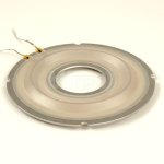
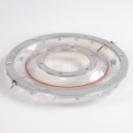
How about forming larger ring radiator diaphragms from PETG or PEEK? Imagine something like the B&C DCX464 or BMS 4590 mid diaphragms in the photos, but larger and conical or approximating a section of the WG, plus the required wiggles that are part of the diaphragm's shape, instead of flat, as if the outer and inner the metal rings were the edges of the outer and inner parts of a printed WG, like in the second picture #15176 The point is that the surround is included in the diaphragm and vacuum forming and gluing is achievable for DIY, probably.
Those B&C and BMS diaphragms have 2.5" and 3.5" voice coils and Sd of 50 ~ 60 cm2, if I remember correctly. That's too small for 200Hz, should be a ring with more like double the Sd.
Below would come the voice coil, if it was an imaginary scaled up driver that would imply a very large voice coil and magnet diameter. Maybe some odd thing created out of a cone driver could drive the diaphragms, something like truncating the cone a 12" midbass to the fitting diameter and gluing cylindrical element onto it to hold the diaphragm.
Attachments
I think that if one took away the professional requirements from CDs, i.e. power/spl and size aspects, there should be possibilities for radically better CDs so I think all ideas like above are really interesting 🙂
//
//
Agreed, especially if you design the CD and horn together, optimizing both to work together as system. Just like how a cartridge, tonearm system is best designed together, though rarely done for some unknown reason.
Example is the exit waveshape of the CD, it may be easier to produce a more uniform curve wavefront than a flat plane wavefront, then design the waveguide to best couple to the curved wavefront. The other is to have the CD have a rising response curve to compensate for the falling response of a CD waveguide. Although, if this were easy it would have been done long ago.
I don't think it's easier. The real difficulty is that all the parts of compression drivers don't behave in a simple way. Whatever exit wavefront shape you choose as a design goal, the real problems are almost always elsewhere.Example is the exit waveshape of the CD, it may be easier to produce a more uniform curve wavefront than a flat plane wavefront, then design the waveguide to best couple to the curved wavefront.
I was not intimating that CDs were simple devices, but that instead of creating a "industry standard" exit angle, you can tailor it to the specific horn design. One of the challenges of deciding on a CD is that it behaves differently on every horn it is coupled to. The industry used to publish plane wave data, which was a bit more universal, but still doesn't give you all the information necessary to predict the final output. Your search for a replacement for the DFM-2535 exemplifies this issue. You can design the horn to work optimally with a specific CD, but what if they discontinue it?
The point is that there's hardly ever an actual planar wavefront, even if the goal is such. And if the goal was different, it would be hardly met, IMO. Although the latest Lavoce drivers tested seem to have unsually clean exit wavefronts. I also think that the influence of an exit angle tends to be overstated, in the light of all the things that matter in the end.
Here's an example - 18Sound NSD1095N with two different throat adapters with the A520G2 waveguide:


The bottom one should be a closer match to the driver. Is it actually?
Here's an example - 18Sound NSD1095N with two different throat adapters with the A520G2 waveguide:
The bottom one should be a closer match to the driver. Is it actually?
Last edited:
The top octave of the DF10.171K is almost textbook-perfect regarding coherency, there must be only very little of any wavefront disruption. It almost makes me think about trying a wave-shaping plug for this one again.
Either a very good job by the Lavoce engineers, or a great luck 🙂
ST260 waveguide + DF10.171K

- Looking at the basic resonance, maybe it should be indeed tried without the rear cover (or with a bigger, well-damped one).
Either a very good job by the Lavoce engineers, or a great luck 🙂
ST260 waveguide + DF10.171K
- Looking at the basic resonance, maybe it should be indeed tried without the rear cover (or with a bigger, well-damped one).
Last edited:
You can achieve good results in any size. Or do you mean that the dome tweeters tend to be smoother, even in small waveguides? Yeah, I guess that's because of the simpler radiation conditions. When you don't need the high-power output a CD can provide, like in a small near field monitor, there's no reason why not use a direct-radiating tweeter.
Last edited:
- Home
- Loudspeakers
- Multi-Way
- Acoustic Horn Design – The Easy Way (Ath4)