Yeah, that's very very similar - I could well get to something quite close I suppose. Why did you take the fins out?
- My basic understanding is that less energy is radiated into farfield and more is stored in the medium within/around the device. But how that works in this case, I have no idea. It has to do something with the bending 🙂
- My basic understanding is that less energy is radiated into farfield and more is stored in the medium within/around the device. But how that works in this case, I have no idea. It has to do something with the bending 🙂
Last edited:
2-inch throat, 4 channels, the whole device is ⌀350 x 185 mm 🙂
- Time to print and test some of it, I guess.
- Time to print and test some of it, I guess.
Attachments
Last edited:
I was trying to simplify the model to avoid crossed surfaces as the first try seemed weird with them, most of the unexpected RadImp didn't change.Why did you take the fins out?
Don made a more conformal simpler mesh and smoothed the RadImp which gave this
Attachments
nice! claiming the promise. Top octave looks like it was 1" throat! Surely time to print and measure before optimizing further. Really cool!
Last edited:
I don't have an explanation but I see something very similar in a simulation I have been running trying to model a Yuichi A-290, when I take the fins out. A peak at a lower frequency which trends back up.
TAD TH-4001 has similar problem with radiation impedance irregularities.

It's actually better than 1" throat. Well, at least in simulation. Typically a 1" throat loses it around 15 kHz, both in theory and practice (2" around 7.5 kHz). This is not the case with any of these, which is of course due to the spherical driving. Now the only question is how close can we get with a real driver. The cleaner the exit wavefront, the better.Top octave looks like it was 1" throat!
Attachments
Last edited:
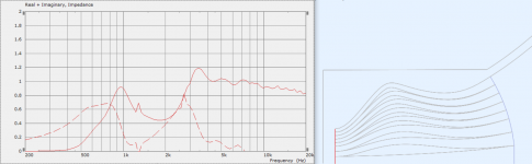
4 channels, 1.4" driver. Does anyone have an explanation why is the impedance as it is? It's obviously a propetry of the bended channels, it's a pattern that will probably stay there.
The local minimum on the impedance curve seems to correspond somehow to the length of the channels (wavelength of 1800 Hz ~ 2x channel length).
Which aspect are you referring to, the overall shape of the response or the change as you ‘flatten the curve’?
The latter appears to be the trade-off between the loading and coverage pattern or the wavefront sculpture. That’s not so dissimilar to the effects of constant directivity horns, trading axial response for more consistent coverage.
One problem with purely numerical modelling like this is the difficulty relating the large amount of data generated to a particular property. The benefits of analytical or semi-analytical modelling, is the ability to define some parameters that change, to easily test a theory. You’re most of the way there with Ath scripting and how quickly you can test different geometry.
I think this method is especially good as a basis for asymmetrical coverage. If you look at some of the line array waveguide approaches, Adamson’s and RCF’s TT series, in particular. They’re using a very similar approach in one plane but converging closer to the classic DOSC shape on the other. Since the axisymmetrical model suggests good results in a ‘slice’ it should just be a matter of finding the suitable equivalent profile for the desired coverage or wavefront shape in the other axis and lofting between them with some smoothing parameters.
4 channels, 1.4" driver. Does anyone have an explanation why is the impedance as it is? It's obviously a propetry of the bended channels, it's a pattern that will probably stay there.
The local minimum on the impedance curve seems to correspond somehow to the length of the channels (wavelength of 1800 Hz ~ 2x channel length).
To me what you have are two devices that are not well matched to each other. One is tune low and the other much higher up. I'd suggest that the higher bumps correspond to the inner channels and the lower bump results from the outer portion. You have an impedance mismatch at the junction.
I have suspected all along that we can't go changing path shapes willy-nilly as the angular portion of the wavefront cannot be spread arbitrary. It is locked to the radial flaring of the waveguides. In math-speak, the equations are coupled and cannot be separated - what you do in angle affects the radial and visa-versa.
The sim is telling you exactly what the equations say.
Last edited:
Well, it's a common thing in audio that we are standing on the shoulders of giants, and in life that 'everything is a remix'. These avenues have been explored by Laurence Dickie of Bowers & Wilkins' Nautilus fame, when he designed the Polyhorn and Dendritic waveguide for Turbosound (pre-Behringer days):


And what seems to be a third party attempt at the same thing:

I've heard the Turbosound Aspect series a whole bunch of times, and they do sound really good. The HF is much closer to the sound of a paper cone than other compression driver loadings of that era. Unfortunately that was possibly their downfall, as the product deviated a lot from what Turbosound was known for sonically - and of course, it was a point source product released during the rise of line array dominance.
Perhaps mabat just needs to add many more channels 😀
And what seems to be a third party attempt at the same thing:
I've heard the Turbosound Aspect series a whole bunch of times, and they do sound really good. The HF is much closer to the sound of a paper cone than other compression driver loadings of that era. Unfortunately that was possibly their downfall, as the product deviated a lot from what Turbosound was known for sonically - and of course, it was a point source product released during the rise of line array dominance.
Perhaps mabat just needs to add many more channels 😀
Last edited:
It's interesting that the channels on the Turbosound plug subdivide. That could be interesting to test.
What if the channels are way longer, so the problem is pushed further down in frequency?
What if the channels are way longer, so the problem is pushed further down in frequency?
Last edited:
To me what you have are two devices that are not well matched to each other...
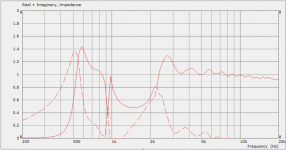
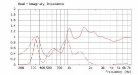
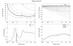
I think that the problem is improper geometry of the petals/channels in the mabats horn which, in essence, in current geometries are a simple curved tubes loaded (damped) with a horn radiation resistance. To test this I simply modeled one of the horn with petals uploaded here by mabat (script sc36) and then modeled radiation impedance of the petals itself.

Simulated impedance is as follow

In my opinion, everything is obvious here.
What's less obvious is optimal geometry of the channels. I believe that the channels themselves should be more like horns, or their length must be of a certain value (or both together)
Last edited:
It's interesting that the channels on the Turbosound plug subdivide. That could be interesting to test.
What if the channels are way longer, so the problem is pushed further down in frequency?
Dr Jack Oclee-Brown had a patent issued for a similar device a few years back that may also be of interest:
US20210110808A1 - Acoustic waveguides
- Google Patents

Thanks that is useful to see that my simulation is not totally borked 🙂 Do you think that the peaks in between the lowest one and where the response settles down are due to the fins and the splitting of the sections?TAD TH-4001 has similar problem with radiation impedance irregularities.
Do you have any idea of what might be done to improve on it?
Dr Jack Oclee-Brown had a patent issued for a similar device a few years back that may also be of interest:
US20210110808A1 - Acoustic waveguides
- Google Patents
That looks interesting too!
I was thinking of trying something like that. Spinning instead of meandering radially.
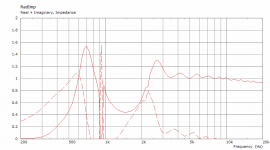
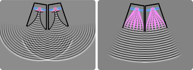
It seems that petal itself introduces some pipe-like resonance. I tried to simulate 4001 with ant without petals and it is seen that petals certainly increases acoustic loading in certain frequency range (approximately one octave above cutoff). It seems to me that this is due to heavily damped pipe resonance.
On the other hand, the radiation resistance of TH-4001 with petals removed itself is highly disturbed, which indicates a problem with the horn walls non-optimal expansion. 4003 is much better in this respect.

On the other hand, the radiation resistance of TH-4001 with petals removed itself is highly disturbed, which indicates a problem with the horn walls non-optimal expansion. 4003 is much better in this respect.
Last edited:
Now this is getting really interesting, thank you all for you contribution of ideas about the acoustics involved. Much appreciated. I'd love to continue in this debate and perhaps gather a better understanding of the matter.
My initial notion was that there willl be no reflection back (i.e. no resonance) as long as the summed wavefront formed will match what's expected at the waveguide entrance. But maybe it's more complex than that.
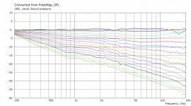
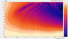
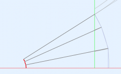
Basically, what we have here as a beginning is this:

There should be no mismatch or resonance whatsoever as, as a whole, it's in fact still one conical device. The only differences to what I presented (besides the fact that the individual sources are flat, not spherical, but that's a very subtle difference, I assume) is that:
- the channels are re-arranged and bended so that the input wavefront forms a line, not an arc
- the individual expansion(s) of the channels can be changed from conical to something else.
So what exactly is it that makes the results so different?
My initial notion was that there willl be no reflection back (i.e. no resonance) as long as the summed wavefront formed will match what's expected at the waveguide entrance. But maybe it's more complex than that.
Basically, what we have here as a beginning is this:
There should be no mismatch or resonance whatsoever as, as a whole, it's in fact still one conical device. The only differences to what I presented (besides the fact that the individual sources are flat, not spherical, but that's a very subtle difference, I assume) is that:
- the channels are re-arranged and bended so that the input wavefront forms a line, not an arc
- the individual expansion(s) of the channels can be changed from conical to something else.
So what exactly is it that makes the results so different?
Attachments
Last edited:
- Home
- Loudspeakers
- Multi-Way
- Acoustic Horn Design – The Easy Way (Ath4)