I have the factory brochure and my dealer binder. No where does it list the weight. All the other dimensions, but no weight? Weird. Sorry.I search with no luck in finding what the weight of the Acoustat Spectra 6600 panel and interface.
I know, I have the manual as well and surprised no weight indicated. I can lift the speaker, my guess its around 100lbs. The reason it would be nice to know is I am going to use IsoAcoustic feet on my custom platform
The other poster stated his 3's weighed 73 pounds. You are only adding three plastic panels and a little of frame, so maybe 20-25 pounds. I would say around 100 pounds would be pretty close...I know, I have the manual as well and surprised no weight indicated. I can lift the speaker, my guess its around 100lbs. The reason it would be nice to know is I am going to use IsoAcoustic feet on my custom platform
I think the Spectra series used only one. Maybe a bigger unit, but pretty sure it was just a single?Two interfaces per speaker
https://www.usaudiomart.com/details...6600-electrostatic-speaker-96-tall-x-30-wide/
Found this for 33's, add two panels at 5.7lbs each gives you a 105lbs plus a little for the extra wood.

I seriously doubt you will find any audible sonic improvement by performing such modifications. The bias transformer is not like a regular power transformer feeding active electronic circuits that require pristine power. The bias supply's outfeed resistor and the panels' capacitance make for a very long time constant, and therefore the chance of audible noise being introduced is nearly impossible. I generally recommend NO modifications to the bias circuit: they either do not result in audible improvement, or worse, can compromise performance (I've seen some pretty hare-brained ideas come across my desk).Should I Add an EMI/RFI Cap to my Acoustats?
I have Model 3's.
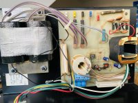
I was thinking to add a capacitor after the fuses, across the AC power in, which goes to the high voltage bias supply transformer. The interface is plugged into a power conditioner. This is to add a last filter on the incoming AC line and to help filter any noise from the bias supply going back to my power conditioner or AC line and thence to other components. I was thinking of a polypropylene cap, around 0.1 uF, safety Class Y2 * (In failure mode it opens, not a short circuit).
I had first selected a capacitor with longer leads, but it's not in stock. So, with lower ESR (electrical series resistance) than a less expensive one (lower is a good thing), this cap I can make fit:
EPCOS-TDK B32023B3104K000
https://www.digikey.com/en/products/detail/epcos-tdk-electronics/B32023B3104K000/3489494
Have you tried this?
What was the result?
Is there any downside to doing this?
Note: also in this bias circuit I am planning on adding the snubber circuit after the transformer, per the thread:
Transformer Snubbers See posts 1, 25.
(Linked to from Post 2,176 of this thread.)
I do not think the snubber will interact (much) with what I propose, which has a different purpose. But I am not an EE, so I am asking.
Brandon
* Note: I found a good explanation of Class X and Class Y capacitors here:
https://www.allaboutcircuits.com/technical-articles/safety-capacitor-class-x-and-class-y-capacitors/
That being said, I don't think your suggested mods will do any harm if done properly, except for wasting your time and money. If you hear a difference, it's only because you want to hear a difference (called expectation bias, no pun intended). I think having your speakers plugged into a power conditioner is overkill, and therefore certainly any additional attempts at power conditioning are more overkill. Sit back, listen, and enjoy.
All of the Spectra full range models use one interface per speaker, of the same case size and style*. If anything, the Spectra 4400 and 6600 interfaces might weigh a little less (1-2 pounds), due to the absence of the HP crossover components used in the Spectra 2200/3300. And sorry, I have no documents indicating weight of any of the models, other than what might be in publicly available brochures, etc. It's just not a question that comes up.I think the Spectra series used only one. Maybe a bigger unit, but pretty sure it was just a single?
https://www.usaudiomart.com/details...6600-electrostatic-speaker-96-tall-x-30-wide/
*The original Spectra 2 and 3 (hybrid design with built-in woofer) use a plate-style interface mounted in the woofer enclosure. Not many of these were made, and I think even fewer have survived.
Hello Andy . i am hoping this is the right way to contact you , i have of Spectra 11 that worked ok until a couple of years ago , but there has always been an issue with the power adaptors , ( i live in Denmark ) , when i bought the speakers the originals adapters came with it , but always had to fiddle where they you plug them with them to get em to work , until finally they did not work at all , i found replacements that were not the best , the also ceased to work , then i got those multi volts adapters and they work , but one of the speakers sound diminishes after a couple minutes and i do not know what causes it . i have other speakers , but i really ike the sound of them , at first i used a Nakamichi 7 and they sounded sweet , and now i have a French Tube Amplifier Audiomat , really well made that most speakers sound great .Hello Audio Enthusiasts! Some of you may know my work on www.audiocircuit.com, where for many years I have been helping to advise Acoustat owners. I was an engineer and manager with Acoustat, starting when the David Hafler Co bought Acoustat out of bankruptcy, right up to the very end of US production under Rockford Corp ownership (sad day that was!). So I thought I'd lend a hand here, too, because I LOVE Acoustats and want to help as many owners as possible to keep their Acoustats running for many years to come. I don't sell parts or do repairs, but my advice is FREE! So let me know how I can help YOU with your ACOUSTAT's! (And this being a DYI crowd, I don't mind discussing modifications to the speakers.)
Andy Szabo
I got my first taste of electrostatic speakers called La folia , great sounding beasts , since then ive had two pairs of Quads es 57 s , but i stil prefer the Acoustats , and i cannot seem to have the heart to get rid of them , could it be that the ES panel is defective or perhaps the crossover ? , any thoughts would be much appreciated .
sincerely
Julian
I have very little Accoustat experience other than the Model X. That was the only thing sold in this area so that’s all I ever saw back in my shop days. That being said, I have a set of Acoustat 2+2 with the MK-121-2A. These appear to have been modified and I must admit I don’t understand the modified bias circuit. Everything I have found online says this thing should produce about 5KVDC bias voltage. The schematics online are not even close to what this is using. There are only 4 diodes are in a bizarre arrangement and the 500 Mohm resistor has been replaced with a jumper. Additionally there is a 0.001uf capacitor filtering the final output. This is producing a negative 600VDC with 180 or so Vpp.
Could the Accoustat Answer Man or someone more knowledgeable than me take a look at the schematic I drew and help me figure out what’s going on. These do work but they don't sound very good.


Could the Accoustat Answer Man or someone more knowledgeable than me take a look at the schematic I drew and help me figure out what’s going on. These do work but they don't sound very good.
Music Geek - I'm afraid your speakers are the victims of a well-intentioned, but hare-brained modification to the bias supply. I've seen this before. Simply put, you should return the bias circuit to its original configuration. Removal of the 500M-ohm resistor changes the fundamental operation of the speaker from constant charge to constant voltage. The latter mode is well known to create higher distortion levels, since the charge on the diaphragm will be constantly changing. You will find that virtually every ESL ever produced (and certainly all of the successful ones) has a high-value resistance between the bias supply and the diaphragm. Would you want a conventional woofer where the strength of the magnet was constantly changing? HECK NO!
The capacitor on the output is unnecessary and can lead to a much greater chance of a dangerous shock to personnel. Any why anyone would decrease the number of stages in the voltage multiplier is unfathomable to me.
Due to the age of the speakers, and the fact that you are missing a multiplier stage, I recommend replacing all of the diodes and capacitors in the multiplier. See attached document for modern equivalents. The fact that you are reading a negative bias voltage suggests that the modifier also reversed the polarity of the diodes. Be sure to orient the diodes properly to yield a positive bias voltage.
You'll also need to find new 500M-ohm resistors. I suggest the surplus market for those. Resistance value is not super critical, probably anything in the 300M-600M-ohm range is fine. Make sure the part is rated for at least 5kV and will fit on the board. Wattage rating is not really an issue in this application, as a sufficient voltage rating will pretty much guarantee that the wattage is also sufficient.
BTW, once you return the bias supplies to original, a conventional HV probe will not measure 5000 volts DC - it will measure only about 3000-3500 volts due to loading of the supply by the probe. This is normal.
I would also suggest checking over the schematic of the rest of the interface and comparing it to the original. It appears the C-Modification has been done but based on the damage done to the bias supply, you should check it for any other modifications. A schematic with the C-Mod is attached.
I'm curious - I see that the original pin receptacle for the red wire, and the thumb screws for the white and blue wires, have been removed. How are the panel wires connected to the PC board?
Attachments

iBUY - it's unlikely you have a defective panel. My suspicion would be with the bias supply, or perhaps the connection where the wall transformer connects. If you're having intermittent contact at the jack, the jack is easy enough to replace - it's an independently mounted, generic 3.5 mm jack.
You should also check the attached documents to see if the bias supply needs to be modified. If so, this may solve your problem, and it's inexpensive and easy to do (assuming you have the requisite skills).
You should also check the attached documents to see if the bias supply needs to be modified. If so, this may solve your problem, and it's inexpensive and easy to do (assuming you have the requisite skills).
Attachments
Acoustat Answer Man. Thank you for your help. The - Bias voltage confused me and, like I said, I'm not overly familiar with these so it's good to hear from the expert. I'm looking at these for the resistors: https://www.mouser.com/ProductDetail/Ohmite/SM108035006FE?qs=SR60igVWod0LkwVbstG/Ow==. If may be a little overkill but it appears to be a limited selection in that value range.
I took the thumb screws out in order to get to the board. One unit has the original pin connector for the red Bias wire the other doesn't and is just soldered next to the pin receptacle.
I took the thumb screws out in order to get to the board. One unit has the original pin connector for the red Bias wire the other doesn't and is just soldered next to the pin receptacle.
Those resistors should be fine. Acoustat used that type as an alternate when we couldn't get the usual ones.
Thanks again. I ordered the HV diodes and caps you suggested. I also ordered the Parts-Express 027-122, 027-118 and 027-100 Audyn caps for the audio section. Hopefully that was a good choice.
Thanks very much for your quick response , it sound like is good news that the problem might not the panels , i have changed the 3.5 mm jack , however both of the wires are the same color (green) and yes i checked with the multimeter to verify + & - , i read the file about the Bias . THANKS , i will look and see what i can find , although i might have all the necessary skills i do not lack enthusiasm , thanks again , happy holidaysiBUY - it's unlikely you have a defective panel. My suspicion would be with the bias supply, or perhaps the connection where the wall transformer connects. If you're having intermittent contact at the jack, the jack is easy enough to replace - it's an independently mounted, generic 3.5 mm jack.
You should also check the attached documents to see if the bias supply needs to be modified. If so, this may solve your problem, and it's inexpensive and easy to do (assuming you have the requisite skills).
i have taken photos of crossovers of the Spectra 11 , the BIAS seems to be sealed , i cant really see to which "V" they are sat to , i am assumimg that it should 15 V , as that is what it says in the adaptors , hence the voltage in Denmark it 210 /20 VoltsThanks very much for your quick response , it sound like is good news that the problem might not the panels , i have changed the 3.5 mm jack , however both of the wires are the same color (green) and yes i checked with the multimeter to verify + & - , i read the file about the Bias . THANKS , i will look and see what i can find , although i might have all the necessary skills i do not lack enthusiasm , thanks again , happy holidays
Attachments
Troubleshooting Guide to Acoustat Speaker Problems
It looks like Acoustats will be here for a long time, so I have gathered some of our repair knowledge into one summary.
My various repairs and experiments have proven to my satisfaction that it is critical that the Acoustat speakers first be made to function (not necessarily appear) as closely as possible to what was intended at the factory – which makes a huge difference – and THEN modifications can be most gainfully performed / added.
I'm hoping this will save on answering some of the same questions over and over. Together with the Acoustat White Paper in this Page (Note: don't believe every tweak you read) and an owner's manual, these give a foundation to anyone wanting to repair their speakers. Also more material from Mr. Szabo is referenced in Post 1,851.
You can direct common questions to this post / Guide.
Note: Some symptoms in the Guide are similar so read carefully.
My knowledge is not as extensive as Mr. Szabo's and I have not repaired other models but these repairs should apply to all models. Let me know if I missed on something important.
Brandon
Attachments
Troubleshooting Guide, more about
Here is a table of contents from the first page of the Troubleshooting Guide in the previous post.
For each symptom there are possible causes given and what the fix is for each.
SYMPTOMS:
1, 2. LOOSE BASS, and /or Slapping Sound
3.A. BUZZING sound
3.B. RATTLING sound
4. A PANEL HAS WEAKER OUTPUT
5. WEAK SPEAKER (ALL PANELS)
5-B. SOUND SLIGHTLY WEAK, one speaker, all panels
6. DEAD SPEAKER
7. ARCING SPEAKER
8. HIGH PITCHED WHINE OR T-T-T-T- SOUND OR HISSING, (not loud), continuous
9. WEAK BASS OR WEAK HIGHS (one speaker)
SPECIAL CASES:
10. Mild Popping or Static / Hissing in first few minutes after plugging in (but not visible arcing)
11. Speakers don’t play or have greatly reduced volume when humidity is high
12. Weaker in Midrange
Brandon
Having restored and did the CMod on the interfaces on my Model 3's, I hooked them up to a McAlister Audio 75/ch tube amp and all was wonderful ! Then I hooked them up to a Classe Audio DR-2 amp and whatever I liked about them before was multiplied a few times!
So now I wonder about the Medallion transformers. short of picking up a pair of complete speakers has anyone tried to reproduce these transformers? I'm sure they wouldn't be cheap. Curiosity could be getting the better of me.
So now I wonder about the Medallion transformers. short of picking up a pair of complete speakers has anyone tried to reproduce these transformers? I'm sure they wouldn't be cheap. Curiosity could be getting the better of me.
- Home
- Loudspeakers
- Planars & Exotics
- Acoustat Answer Man is here