Are 5 wire non spectra panels segregated in middle? If not, there should be no difference between 3 wire and 5 wire non Spectra panels...correct?
Spectra panels have 5 wires, with the stator split in the middle. A Spectra panel can replace any other 5-wire panel by connecting the two front and the two rear stator wires together, just as you would a regular 5-wire panel. A Spectra panel can even replace a 3-wire panel with the same connections. All Spectra panels have the improved conductive coating, and of course represent the newest panels out there.
I want to wish all members of this forum a happy new year and that Acoustats still live on and on, thanks to a few passionate members here.🙂
I have seen it mentioned several places that all Spectra panels are the same, having stators that are split in the middle of the panel.Spectra panels have 5 wires, with the stator split in the middle...
I'm not sure if the term "middle" was meant to be specific(as in split exactly into two equal sized sections) or just general.
Could you clarify?
Both the Spectra 11 and 1100 models I have worked on had the stators split into roughly 3" and 6" widths(ie not the middle).
This seems to agree with the descriptions in the manual for the Spectra 11.
I have not personally seen any of the larger Spectra models.
But, the manual description for the Spectra 22 also agrees with the use of two panels having identical stator section widths of 3" & 6".
Attachments
I have seen it mentioned several places that all Spectra panels are the same, having stators that are split in the middle of the panel.
I'm not sure if the term "middle" was meant to be specific(as in split exactly into two equal sized sections) or just general.
Could you clarify?
Both the Spectra 11 and 1100 models I have worked on had the stators split into roughly 3" and 6" widths(ie not the middle).
This seems to agree with the descriptions in the manual for the Spectra 11.
I have not personally seen any of the larger Spectra models.
But, the manual description for the Spectra 22 also agrees with the use of two panels having identical stator section widths of 3" & 6".
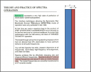
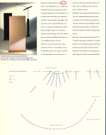
To the best of my memory, all Spectra panels are physically divided into two equal halves. That was the design intention of the Spectra technique. Any references in marketing literature to panel widths refer to effective panel width at a particular frequency.
If you have observed panels that were physically divided into unequal segments, I am at a loss to explain that. I will have to dig out my slides of the panel manufacturing process to see if the equal-halves segmentation is clearly shown.
Thanks for the clarification/correction.To the best of my memory, all Spectra panels are physically divided into two equal halves...
It has been a while since I looked at a Spectra panel and was going on memory and scribbled notes where I had the width of the full range section identified as ~3”. As soon as I started reading you reply I realized the 6” section width I had calculated (ie 9” – 3”) was incorrect since the total width of the light louver is 9” and the outer two rows of cubes do not have any stator wires on them. That is what I get for trying to match numbers in a manual 😉
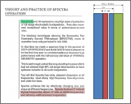
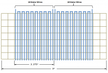
Based on your description and photos in your factory tour document, I created a diagram showing the width for each of the stator sections as 3.375”. I’d say that qualifies as about 3”, as mentioned in the manuals. The midrange width for the Spectra 22 would then be 13.25” which is about 13” as mentioned in the manuals. The only outlier is the Spectra 11 manual which had the midrange width listed as 9”.
Interestingly enough, I stumbled on a Spectra Brochure which identifies the width of the full range section as a pretty specific 3.3”.
Note also the figure at the bottom clearly showing equal widths for all the stator sections.
Attachments
Thanks for the clarification/correction.
It has been a while since I looked at a Spectra panel and was going on memory and scribbled notes where I had the width of the full range section identified as ~3”. As soon as I started reading you reply I realized the 6” section width I had calculated (ie 9” – 3”) was incorrect since the total width of the light louver is 9” and the outer two rows of cubes do not have any stator wires on them. That is what I get for trying to match numbers in a manual 😉
Based on your description and photos in your factory tour document, I created a diagram showing the width for each of the stator sections as 3.375”. I’d say that qualifies as about 3”, as mentioned in the manuals. The midrange width for the Spectra 22 would then be 13.25” which is about 13” as mentioned in the manuals. The only outlier is the Spectra 11 manual which had the midrange width listed as 9”.
Interestingly enough, I stumbled on a Spectra Brochure which identifies the width of the full range section as a pretty specific 3.3”.
Note also the figure at the bottom clearly showing equal widths for all the stator sections.
Yes, there are some conflicting descriptions of sector width. Most references are effective width, but it doesn't help matters when some were further rounded off from 3.3 to 3. The Spectra 11 manual is clearly using 9" as meaning the entire panel, even if the effective width is only 6.75". I did come across Jim Strickland's White Paper that includes the Spectra information. Note his reference to a sector width of 3.3 inches.
Attachments
I did come across Jim Strickland's White Paper that includes the Spectra information.
Thanks for sharing this paper...I had not seen it before.
Had you previously posted this over on AudioCircuit? (I can't seem to locate it)
I am searching for the Figures to go with the text.
Thanks for sharing this paper...I had not seen it before.
Had you previously posted this over on AudioCircuit? (I can't seem to locate it)
I am searching for the Figures to go with the text.
It seems that many of the documents I supplied to the AudioCircuit website are no longer available. The Spectra Whitepaper may have been available at one time. I also checked the 'Acoustat CD' I received from Audiocircuit, and Spectra Whitepaper document is not on the disc.
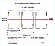
The only figure I could find is attached, which may or may not have been included in the Spectra Whitepaper. I copied this from an early Spectra 22/33 sales sheet.
Attachments
Andy ..having checked bias on newly acquired 2+2 due to popping discharge on one panel, I found it tests out at 79.4vdc while the mate checks in at 73.3. Other than probable volume differences, I assume this could initiate the discharge in the single grid powered by that particular interface. Since these are mk121-2A no transformer update, how do I adjust to 75Vdc bias as well as bring them into balance.......the HF rheostat has been taken offline by previous owner.
how does one adjust bias on mk121-2A.....pair of 2+2s one popping and testing 79.4Vdc the other measures 73.3Vdc.....I doubt this matters but previous owner did take rheostat offline.....so what is the acceptable delta for bias from the 75Vdc quoted by Andy and how can it be handled? Dan
Andy Can one use the acoustat 2+2 interface on a homebrew electrostat setting it for 1 panel?
Thanks Al
Thanks Al
how does one adjust bias on mk121-2A.....pair of 2+2s one popping and testing 79.4Vdc the other measures 73.3Vdc.....I doubt this matters but previous owner did take rheostat offline.....so what is the acceptable delta for bias from the 75Vdc quoted by Andy and how can it be handled? Dan
The bias cannot be adjusted on the MK-121 series. So you're pretty much stuck with whatever variation you have, unless of course the difference is huge, which might indicate a defective component. Replacing ALL of the capacitors in the voltage-multiplier might help to improve the situation, as their value and leakage can degrade over time.
The rheostat has no bearing on the bias voltage. It is used for adjusting the High-Frequency Balance.
Andy Can one use the acoustat 2+2 interface on a homebrew electrostat setting it for 1 panel?
Thanks Al
Of course, you can hook it up to any ESL panel. The "number of panels" setting controls the bass equalization, and can be set to any value you desire.
How well will it work? That would depend on your homebrew panel, 'natch.
Andy ..having checked bias on newly acquired 2+2 due to popping discharge on one panel, I found it tests out at 79.4vdc while the mate checks in at 73.3. Other than probable volume differences, I assume this could initiate the discharge in the single grid powered by that particular interface. Since these are mk121-2A no transformer update, how do I adjust to 75Vdc bias as well as bring them into balance.......the HF rheostat has been taken offline by previous owner.
I see I didn't fully address your situation. I would not expect any correlation between your measured bias values and the popping panels. Yes, one might expect a volume variation between the speakers, due to such a large difference in bias value. But the higher of the two values is not so high as to cause high-voltage breakdown (as witnessed by the fact that some folks add another step to the voltage multiplier, thereby increasing the bias nearly 20%).
The popping panels are a localized non-destructive discharge caused by foreign material caught in the gap. The solutions have been discussed elsewhere (see thread 'Acoustat Answer Man is Here') but the basic idea is to fully discharge the speaker, blow-out both sides of the panels with compressed and/or vacuum. Sometimes the process needs to be repeated for full effectiveness.
Originally Posted by DeltaStar View Post
Andy Can one use the acoustat 2+2 interface on a homebrew electrostat setting it for 1 panel?
Thanks Al
I am using a heavily modified MK-121-2A on a pair of ML CLS panels...as I had way too much bass, even on the 4 panel tap.
I have been using HP filtering the amp to CLS/Acoustat interface at 100hz with very good results with only the HF tranny and no secondary series cap/resistor to panel - as they are no longer needed without the bass tranny. I also needed to reduce the bias voltage all the way down to 3k from 5k as the CLS panel (with newly installed mylar) was "sizzling", by pulling a couple cap/diode pairs.
BTW - The higher the panel taps means less bass - so tap set on 1 panel tap is max bass. At 1 panel tap, isn't bass way too high? Odd noises?
Last edited:
Andy, I feel I have to much bass and it's affecting the lower vocals and causes a veiling so to speak, if I move to three or two, will this cut bass down? Thanks Al
Hi John, I'm on 4 now, these Acoustat 2+2's are wierd, I bought them new in 83, for yrs I wouldn't even use them, they wouldn't work in any of my rooms I put them in, need excessive volume levels to get any amount of sound from them, and bass shy, I set them up in a 3600 sq ft room with 12 ft ceilings and the same amp idles at 95db but to much bass, in that room I cut 3db at 20 hz when equing , My Aps and Infinitys can't even get close 🙂 Al
That is weird - all I can think of is placement issues - I had mine in a smallish 20' x 14' room. They were good, after eq'ing with DEQ2496, everything was all better...
Sounds like Low Bias ........john knows albout the bias...more bias better topend..........but that's just on the 10pr of Acoustats I owned...hehe
Maybe Delta needs the Air mod..Or Mabe just some more segmented ESL panels.........I done my time with ESLs....these old Apogees an maggy have great topend....an can give lots of output with small tubes amps...
Good luck it never ending................well for some...
Maybe Delta needs the Air mod..Or Mabe just some more segmented ESL panels.........I done my time with ESLs....these old Apogees an maggy have great topend....an can give lots of output with small tubes amps...
Good luck it never ending................well for some...
- Home
- Loudspeakers
- Planars & Exotics
- Acoustat Answer Man is here