1+1 Medalion C
Andy playing 1+1 medallion C through PC AND a USB dac , Powered by McIntosh tube amp.
One of the speakers started outputting a very high pitch screeching noise as soon as amp turned on, immediately SHUT IF OFF. The other speaker plays fine. Disconnected both interfaces and side by side did a resistance test on
both interfaces had similar values except when I checked ground to the 3 different points of the high frequency resistor. The good interface would read OL, OL, OL not shorted . Not functional interface read 1.5ohm,3. ohm & 1.5 shorting . So I floated the ground and all resistance measures same on both interfaces. Didn't use a high voltage probe but turned interface on with variac to 60 volts and the power output measurement was consistent to both interfaces. Put a load on the didoes and seem to check out fine. Lifted a couple ceramic 3300 pf caps and tested good. Inspected all caps and resistors no apparent burned or stress markings all look great. Measured resistance on all three transformers and all consistent with good interface.
playing a set of DCM-Timeframes through same amp, dac & PC no issues what so ever. I'm about to pull my hair out would love to hear your thoughts.
My Best,
Andrew Sterling 😕
When you say "checked to ground" do you mean chassis ground? There should be no continuity between any part of the low voltage audio input circuit and chassis ground, so you have some problem there. I would look first for trouble around the terminal strip where the capacitors (and depending on version, resistor) for the HF circuit are located. No part of the circuit should be connected to the lugs that are part of the chassis-mounting lugs of the terminal strip. Also look for inadvertent solder blobs, or stray strands of wire in that area.
Also look for the same problems on the terminal strip that holds the 1-ohm resistor in the LF circuit.
If no problems are found in those two areas, it's possible (though unlikely) that one of the binding posts is shorted to chassis.
Report back with your results. We'll go further if necessary.
Andy going to build new frames from channel aluminum or steel do you have suggestion to which material is best? Will rewire the panels wondering would Cat 5 or 6 be a good type of wire. Cat 5or6 is Teflon coated solid core copper thinking it would be great. If not what do you suggest?
Thank you,
Andrew Sterling
Thank you,
Andrew Sterling
Andy going to build new frames from channel aluminum or steel do you have suggestion to which material is best? Will rewire the panels wondering would Cat 5 or 6 be a good type of wire. Cat 5or6 is Teflon coated solid core copper thinking it would be great. If not what do you suggest?
Thank you,
Andrew Sterling
I have no opinion on frames made of steel versus aluminum. Steel is cheaper. Aluminum is easier to cut/drill. Either way, great care must be taken to ensure the panels and wiring are VERY well insulated from the metal frame. A metal frame may introduce a resonance if not well damped (like filling the frame with sand of some such material).
I see no reason to replace the wires on the panels, as the originals are made of specifically designed, oxygen free, high voltage wire. If you insist on replacing the leads, make sure the wire is rated for at least 10,000 volts (10 kV). I doubt the wire you mentioned is so rated.
Did you get the problem with your interface fixed?
Yes I found the exact same issue before I read your remedy and it was fixed . When reading your remedy I was amazed how you diagnosed the issue so well without seeing the unit. You have Amazing ability to diagnose. Thank you very very much for all your valuable inputs.
Andrew
Andrew
Yes I found the exact same issue before I read your remedy and it was fixed . When reading your remedy I was amazed how you diagnosed the issue so well without seeing the unit. You have Amazing ability to diagnose. Thank you very very much for all your valuable inputs.
Andrew
Thanks, I'm glad you got it fixed. The interface may work in mysterious ways, but component-wise, it's a pretty simple circuit and is generally easy to diagnose. Besides, you gave me some pretty good clues from your resistance measurements!
Hi All:
Anyone come across or have the Acoustat TNP preamplifier? Looking for info and schematics if available. Recently bought and it's quite a nice preamp although the gain seems quite high, i.e., the volume control only requires to be turned a little to get quite loud through a TN-200 amplifier into Model 3s. Doesn't appear to be any way to lower the gain aside from soldering resistors on the outputs or using attenuation adapters, like Rothwells or Endlers.
(There also seems to be possibly an audible hum through the speakers, not through the Models 3s but on a small pair of Sony car speakers that I was using for troubleshooting why I lost one channel, depending how things are connected. The hum also occurred through the speaker level connections of a HSU Mk2 sub. Any ideas? Maybe grounding issue?)
By the way, are all the electronic components/parts, aside form the transformers, for the interfaces still available from various vendors or unobtanium?
Thanks.
Sincerely,
Kingsley.
Here is a pic of the TNP Schematic I used when repairing a friends some years ago.
Looks like a full manual which includes circuit description and parts list can be downloaded here:
Acoustat Trans-Nova TNP - Stereo Preamplifier - HiFi Engine
Looks like a full manual which includes circuit description and parts list can be downloaded here:
Acoustat Trans-Nova TNP - Stereo Preamplifier - HiFi Engine
Attachments

Bolserst - thanks for posting the TNP schematic - it's been a long time since I've seen one. I don't think I have one in my archives.
System hum can be caused by all sorts of issues, from component issues to system grounding. Generally speaking, your system should have only one earth ground, so if you have more than one component with a three-pin line cord, only one should be connected, and the rest should be floated with a three-pin to two-pin adapter. This rule does not apply to the grounded line cords on the speakers: they should be retained for safety reasons. Remember that TV cable connections are another source of earth ground, so if you have one connected to your system, it could be a source of trouble. If the hum started with the installation of the TNP, it could be defective: did you try listening to the headphone output? The TNP is rather old, so you may have one of more faulty filter capacitors. Also, make sure the preamp is not situated on top of the power amp - a bad practice for any preamp/amp combo.
BTW, the reason you heard the hum through the car speakers and not the Acoustats may be a function of efficiency. In others words, the hum may be present in the Acoustat speakers too, but too low in level to be audible.
Parts for the interfaces are obtainable, sort of. The issue is the high-voltage rating of some of the parts, which can make them hard to find. There have been discussions along these lines previously in this thread. Is there a specific part you need?
Last edited:
Thank you very much bolserst for the TNP schematic and the link to the manual! Good to know you've work on one before.
Andy, thanks you also for things to check re: hum. No cable/box since we long stopped the service because we weren't watching TV much and there was just too much garbage and just not worth the monthly fees. Understand the 3 to 2 prong adapter - good thing I don't really need it presently. It was just kind of unusual to hear a hum coming through the powered sub and the car speakers (connected via the speaker level push clips(/?)). I was using a portable Sony CD Walkman connected to the headphone jack (mini stereo to RCA plugs) to the Acoustat TNP and then RCA to RCA interconnects to the TNT-200. The hum was louder through one channel (right) but less when the RCAs were swapped left to right - yes, kind of weird. Yes, Andy, you are correct in that the hum is much less on the Model 3s (can hear the low level hum on the right channel and none on the left.
Don't hear the hum through the headphones. Another weird thing is with the headphone plugged in, the output 1 & 2 switches disengaged, and the volume increased, the right channel on the loudspeaker also produces sound whereas the left doesn't - there is sound through both channels of the headphones. Also, engaging the output 1 switch produces a static pop (quite nerve wracking) though the Models 3s. The static pop (to a lesser extent of course) also occurs when the mute switch is toggled.
Andy, are you referring the power supply caps on the one on the board? There are two large white electrolytics in the power supply and several smaller ones populating the board in three to four areas.
Would soldering a quality resistor of suitable value to each channel output (to reduce the output level and allow the volume control more rotation 11-2 o'clock rather than limit 7-7:30 o'clock) degrade the sound quality?
I can do the soldering and parts replacement myself but don't have enough circuit knowledge nor measuring equipment and therefore may need to take it to a tech to check/go over.
Apologies for being so long winded. Just trying to make the most of this preamp as I think it has some special sound qualities/characteristics (plus it's musical and causes toe tapping!).
Thanks.
Sincerely,
Kingsley.
Hi Andy:
Forgot about the parts aspect. No part in particular at the moment but I thought I might need one/two of those 500MG ohm resistors. I think they are 2W ones? There appears to be a link to similar ones in one of the older posts. if I can find maybe 3W ones, then I take they will work also?
I take it that the monster cable can be replaced with thinner gauge wires like 17 gauge?
Thanks, Andy.
Sincerely,
Kingsley.
Hi Andy,
I have a pair of Acoustat 1+1 medallion mk-121-c which I bought used back around 2000, but I guess were made in the early 90s. They have run flawlessly all these years and I still love them and would never part with them. But for some reason I feel like they sounded better when I first got them, but it could be so many things since I am in a different house and I am older and just going from a feeling/memory.
Is there any sort of "20 year" maintenance which should be performed to bring them back into spec? I remember reading something years ago about using a hair dryer or heat gun to tighten up the Mylar membrane. I also remember reading about how the electrolytic caps can age and need replacing after 20years.
Or am I just better off leaving them alone until some problem appears.
cheers jessica
1+1s came out in 1984.....30years is a long time to have the bias running....Andy can give you input.....even at 30...still great speakers
Hi Andy,
I have a pair of Acoustat 1+1 medallion mk-121-c which I bought used back around 2000, but I guess were made in the early 90s. They have run flawlessly all these years and I still love them and would never part with them. But for some reason I feel like they sounded better when I first got them, but it could be so many things since I am in a different house and I am older and just going from a feeling/memory.
Is there any sort of "20 year" maintenance which should be performed to bring them back into spec? I remember reading something years ago about using a hair dryer or heat gun to tighten up the Mylar membrane. I also remember reading about how the electrolytic caps can age and need replacing after 20years.
Or am I just better off leaving them alone until some problem appears.
cheers jessica
Re-tensioning the diaphragm should not be required merely as a function of age. If you are experiencing an increased amount of rattle or flutter on large bass excursions, then re-tensioning may be in order.
Capacitors can degrade with time, and you may experience some benefit from replacing them. The electrolytics should be the first candidates for replacement, as they are known for aging faster than other types.
If you have access to a high voltage probe, you may want to check your bias voltage. Methods to do this and expected results have been discussed in previous posts. The capacitors and diodes in that circuit may degrade over time. The result of a low bias voltage is reduced efficiency (i.e. requiring more power to play at the same volume).
Finally, the two high voltage capacitors on the printed circuit board are also potential candidates for replacement, although these are probably the most reliable of the capacitors in the unit. They can also be difficult to find with the required 5-kV rating.
Thank you very much bolserst for the TNP schematic and the link to the manual! Good to know you've work on one before.
Andy, thanks you also for things to check re: hum. No cable/box since we long stopped the service because we weren't watching TV much and there was just too much garbage and just not worth the monthly fees. Understand the 3 to 2 prong adapter - good thing I don't really need it presently. It was just kind of unusual to hear a hum coming through the powered sub and the car speakers (connected via the speaker level push clips(/?)). I was using a portable Sony CD Walkman connected to the headphone jack (mini stereo to RCA plugs) to the Acoustat TNP and then RCA to RCA interconnects to the TNT-200. The hum was louder through one channel (right) but less when the RCAs were swapped left to right - yes, kind of weird. Yes, Andy, you are correct in that the hum is much less on the Model 3s (can hear the low level hum on the right channel and none on the left.
Don't hear the hum through the headphones. Another weird thing is with the headphone plugged in, the output 1 & 2 switches disengaged, and the volume increased, the right channel on the loudspeaker also produces sound whereas the left doesn't - there is sound through both channels of the headphones. Also, engaging the output 1 switch produces a static pop (quite nerve wracking) though the Models 3s. The static pop (to a lesser extent of course) also occurs when the mute switch is toggled.
Andy, are you referring the power supply caps on the one on the board? There are two large white electrolytics in the power supply and several smaller ones populating the board in three to four areas.
Would soldering a quality resistor of suitable value to each channel output (to reduce the output level and allow the volume control more rotation 11-2 o'clock rather than limit 7-7:30 o'clock) degrade the sound quality?
I can do the soldering and parts replacement myself but don't have enough circuit knowledge nor measuring equipment and therefore may need to take it to a tech to check/go over.
Apologies for being so long winded. Just trying to make the most of this preamp as I think it has some special sound qualities/characteristics (plus it's musical and causes toe tapping!).
Thanks.
Sincerely,
Kingsley.
I'm not really going to be able to help much with your TNP preamp. I suggest you repost your questions in the appropriate solid-state preamp section of DIY audio. This is an electrostatic loudspeaker thread.
The TNP was once a well-respected preamp, but quite frankly I never lusted for one, even when I could buy one at employee discount (the Acoustat TNT amplifiers are another story entirely). And these days, I wouldn't give you a plugged nickel for a TNP - too many things to go wrong: switches, pots, electrolytics, etc, etc.
Good Afternoon, Andy:
Thank you for taking the time to reply.
My apologies if I have posted in this forum topic that was reserved for 'electrostatic loudspeaker thread' (Acoustat panels and their interfaces). Not sure if posting in the solid state section of diyAudio will solicit much response (aside from the schematic and where to check/what may need to be repaired/swapped/modified) since I suspect not many TNPs were made or not many actually have and use the TNP.
Interesting of your take on TNP even given the number of switches, pots, electrolytics (given that it's not much different from a parts perspective than the vast majority of vintage equipment out there)! You did not indicate whether you have listened to one or not other that the comment 'The TNP was once a well-respected preamp, but quite frankly I never lusted for one, even when I could buy one at employee discount...' Thanks anyway.
Sincerely,
Kingsley.
One of the interface transformers for my Spectra 22's has burnt itself out. Where can I get a replacement or have it (the interface) repaired.
…the two high voltage capacitors on the printed circuit board are also potential candidates for replacement, although these are probably the most reliable of the capacitors in the unit. They can also be difficult to find with the required 5-kV rating.
This reminded me that I had been meaning to post some findings on degradation in these capacitors and one possible replacement path. I was troubleshooting a pair of 1+1s with a noticeable L-to-R imbalance in the midrange. Initial measurements indicated a possible problem with the HF transformer. Further investigation pointed the finger at the mixer capacitors. Swapping with capacitors from another interface confirmed the diagnosis.
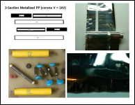
I cut the ends off the capacitor and unrolled the metalized film. Well over 100 damage points were noted where internal corona discharge vaporized the metalized film. As best I could tell, these capacitors used a 3 section configuration which would be good for ~1000VAC based on corona discharge, although they have a 6kVDC rating. For more details see attached PDF on the subject.
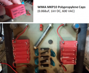
I decided to try “building” a replacement capacitor from a series stack of 6 WIMA MKP10 capacitors. The net voltage rating would be 6kVDC and 3.6kVAC which is adequate for the voltages they will experience in the mixer circuit.
Measured response with the WIMA replacements in the interface matched OEM so I was happy. The owner felt the sound of the interfaces with the WIMA caps were noticeably improved in the midrange…enough so that he had me replace mixer caps in his other Acoustats as well.
Attachments
ebay Acoustat parts....look like one there $250....good luck
The transformer set currently for sale on eBay is NOT suitable for the Spectra 22. Those transformers are for the 44/4400/66/6600 and lack sufficient bass step-up ratio for the Spectra 22/2200 or 33/3300.
- Home
- Loudspeakers
- Planars & Exotics
- Acoustat Answer Man is here