Looks like they added the .022uf 10,000v caps at the output (upper left hand corner)
Must of been a mod, they are not on the non functional amps
Must of been a mod, they are not on the non functional amps
You may be right. There are no holes in the pcb. However, there are a couple of large poly caps on the underside on those.
I can't remember where I saw it, but someone once mentioned "star grounding" in the interface. I had a good look inside and the only improvement I could see is disconnecting the bias board's connection to chassis ground at the mixer board's mounting pillar and running a wire to the green ground wire to where it attaches to the chassis adjacent to the bias transformer. It wasn't obvious to me where the other secondary wire from the bias transformer connects. Does it just connect to chassis ground at the transformer mounting?
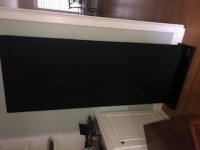
model 3 back panel
I have the Model 3 that is 70"x28". On the back there is an upholstered panel I can't remove. I removed all of the screws and I can pull it back a half inch or so, but it's still attached somehow.
Anyone know how to remove this panel? thank you,
I have the Model 3 that is 70"x28". On the back there is an upholstered panel I can't remove. I removed all of the screws and I can pull it back a half inch or so, but it's still attached somehow.
Anyone know how to remove this panel? thank you,
Attachments

I have the Model 3 that is 70"x28". On the back there is an upholstered panel I can't remove. I removed all of the screws and I can pull it back a half inch or so, but it's still attached somehow.
Anyone know how to remove this panel? thank you,
Those are actually model Three/M. This was also available with a woofer as a Three/MH. That panel was to attach the woofer to.
https://www.vintageshifi.com/repert....php?pdf=Acoustat-Model-3-M-Owners-Manual.pdf
Last edited:
Those are actually model Three/M. This was also available with a woofer as a Three/MH. That panel was to attach the woofer to.
https://www.vintageshifi.com/repert....php?pdf=Acoustat-Model-3-M-Owners-Manual.pdf
Based on the manual you linked it does look like mine are the 3m and likely utilize the same frame as the 3mh but without the woofer option. (Thanks, I never knew why mine were taller that the other 3s.) The woofer would then attach to the space now occupied in my speaker by a black upholstered piece of mdf or plywood. To that piece my interface is attached.
I reviewed the manual and don't see in the description of the 3m or 3mh how to remove that panel. I'm guessing that when delivered as a 3m, the black panel is in place and when delivered as a 3mh it is not attached, as the instructions don't mention removing the panel to install the woofer.
I still need to remove the panel because unfortunately one of the t-nuts that holds an interface screw pushed through and is now rattling around the bottom of the cabinet.
Sure I can remove the cloth top to bottom but that's a huge endevor.
I have not tried removing the bottom base - I wonder if the bottom of my mysterious panel is attached to the base somehow. Any ideas? thanks again,
I used to know this but my memory fails me. What is the high/mid and base cross-over frequencies set up on a 6-pannel Spectra 6600? I hope to someday understand wiring schematics.
Last edited:
Spec sheet for Spectra 11 base speaker attached.
Years ago I got the attached specification sheet from a tech at Rockford Acoustic Designs. They apparently supplied the 8 inch 4 ohm dirver used in the Spectra 11's. No guarantee it is the correct one though.
Years ago I got the attached specification sheet from a tech at Rockford Acoustic Designs. They apparently supplied the 8 inch 4 ohm dirver used in the Spectra 11's. No guarantee it is the correct one though.
Attachments
Last edited:
The Spectra 11 and 1100's used different base speakers. The drivers and the box sizes and cross over circuits were different.
The following are the internal dimensions of each:
The Spectra 11 base had a 45 litre sealed box cabinet 34.5w x 31.5dx 42.5h
Spectra 100 39.5 litre sealed box 36.8 x 36.8 x 29.2
The litre calculations above do not take into account the volume consumed by the drivers.
Apparently the Spectra 1100 driver was of better quality and it has been said elsewhere that change to the lower height box was to accomodate the marketing people.
The box in the 11's was made out of low density particle board and the box of the 1100's was made out of higher density MDF.
All commentators say the 1100 base sounded better and the base in the 11's was it's achillies heal.
The panels on both the 11'ss and 1100's are the same.
I have read that teh "1100's crossover begins to roll-off at 6 dB per octave around 150 Hz, and then steepens to 12 dB per octave above 250 Hz. The woofers are capable of credible bass response down to at least 40 Hz. And they were actually designed for rather low efficiency, to match the low efficiency of the electrostatic panels."
I am looking to upgrade the base in my Spectra 11's and thouht I would build a new box out of MDF. This could even insert inside the existing particle board box and be of a smaller volume or could be a complete new box.
A box inside the box would be big enough to either accomodate 8 inch or 10 inch drivers.
Keen to hear peoples suggestion for possible drivers and box choice (sealed vs vented).
What I well say About the spectra 11.....Is that I always thought the base driver was lacking till I got the bias on this one panel up to 5k....info on cking bias is here,look to see how to ck with a reg type voltage metter.
I sead before here that in the south fl....11s come up for sale a lot...I had 4-5 pr
paid $30 for the last pr, why, one panels had low output....out of all I have owned from the pr I got back in the 90s, till to day none, even the ones that played, so the owner thought, both panels had output...those go for $200-50 pr here.....None had 5k bias...Just like most of the full rang don't have 5k today
So I set out to rework the bias parts an do the mods like the red wire,that well give 3-500-2k volts or more...After getting the Bias up to 5k....the base driver, has never souned better
you can ever tell it there...the 11s just sound like one of the best full rang ESL I have ever owned...By the way for me after owning over 20 pr of full rang Acoustats….to my ears the 1+1 an the Spectra 11 are the best sounding Acoustat ever!...but still my Martin Logan CLS still the winner!
All just one mans o-pine..
Yes dropping the panels down like the Z11 so the panels about 8-10" off the floor an getting the middle of the panels at ear shot is better..
Word to the wise...No matter what you do to any Acoustat ESL get the bias up to 5k!
To day I am playing a pr of 1+1 as I type...ruing them off a stock Dynaco st70...how the bias is at 5k....have fun good luck
Tyyu thanks for the info. Will set the bias in the next few days. Need to source a meter with 10Mohm input as mine is somewhat less.
Mine hcame new with all the upgrades including the red wire bias upgrade - which you mentioned. I think that was just a stability upgrade not a sound quality upgrade.
Have just replaced all the electrolytic capacitors in them and will also upgrade the 100 ohm microfarad electrloytics that are in the signal path with a Solen Polypoplene shortly to see what difference that makes
I run mine off an Acoustat TNT-200 amp now (best amp I have ever used with them) and I am about to refurbish this.
At some point I may also upgrade the base speakers and the base speak box (more internal bracing) with these speakers some Dayton-audio-rss265hf-4-10. which on their specs look like they may possibly be a good match. I determined this by entering their small thiel values into WinISD along with the size of the base speaker box.
Dayton Audio RSS265HF-4 10" Reference HF Subwoofer 4 Ohm
Spec sheet for Spectra 11 base speaker attached.
Years ago I got the attached specification sheet from a tech at Rockford Acoustic Designs. They apparently supplied the 8 inch 4 ohm dirver used in the Spectra 11's. No guarantee it is the correct one though.
I would be suspicious of this spec sheet. It is dated 1996: Rockford dumped Acoustat years before that, and Rockford's speaker division was known as Rockford Carbonneau at the time they produced woofers for Acoustat. It may be a similar woofer, but it ain't the real thing.
Questions to those that have re-socked using spandex milliskin: I read that stretching it roughly twice it's resting width is about right for optimum transparency, but how much are you stretching it in the vertical direction? Does stretching it a lot in one direction make it less stretchable in the perpendicular direction?
Questions to those that have re-socked using spandex milliskin: I read that stretching it roughly twice it's resting width is about right for optimum transparency, but how much are you stretching it in the vertical direction? Does stretching it a lot in one direction make it less stretchable in the perpendicular direction?
Here is the fabric I used:
Mellotone Premium Black Speaker Grill Cloth Yard 64" Wide
It stretches in the horizontal plane, but not so much in the vertical.
Just a quick update to this thread. Earlier I mentioned that I had reduced the size of my Spectra 11 base cabinets by stacking magazines in them. This worked well for the sub optimal placement I had them in (in an odd shaped room). I have now moved them into a much better placement and I found removing the magazines (so they are now as per original) suits their new conventional placement much better.
How were the wires routed within the frame in the Plus models? I've modified my 3-wire panels to be 5-wire and I started wondering if there's any advantage to grouping the cables in any particular configuration? If you let the wires from the upper panels just fall naturally from the panels, you end up with two pairs of signal wires, each comprising a blue wire and an opposite flow of current white wire (which would mostly cancel any magnetic field emanation.) Would it be better to group them as two pairs each comprising the same colour wires and allow a greater field and its greater proximity effect at higher frequencies causing higher effective resistance in order to lower arc-over potential?
Last edited:
I can't speak for certain on how the wires were bundled/routed in the Plus series (1+1, 2+2, 6, 8). But I can say that in the Spectra models, we bundled all the bias wires together, all the front stator wires together, and all the rear stator wires together. PVC tubing was used to aid in that grouping. Magnetic effects are negligible here - because currents are negligible.
Grouping wires this way may have a slight advantage in reliability, in that it groups like-voltage wires together. Should there be a nick or failure in the wire insulation, this reduces the chances of arcing between wires. Voltage differences between front and rear stator wires can reach 10-Kv, so this is not insignificant and it's best to keep them apart.
Grouping wires this way may have a slight advantage in reliability, in that it groups like-voltage wires together. Should there be a nick or failure in the wire insulation, this reduces the chances of arcing between wires. Voltage differences between front and rear stator wires can reach 10-Kv, so this is not insignificant and it's best to keep them apart.
- Home
- Loudspeakers
- Planars & Exotics
- Acoustat Answer Man is here