I don't think so, the reason is the floor bump has changed. Worth a try perhaps but that first cycle plot being without a dip tells me the floor bump was eating away the output.
Getting the woofer closer to the floor means having these two (the woofer plus its virtual mirror partner) closer aligned.
Think of the YG Acoustics who use that solution too:

Not the only one out there, just an example of it.
How many do you know that use more than one woofer there. I can think of many that go with that solution. Making that double woofer more vertically directional, because of the individual differences to their floor mirror counterpart. They are averaging room (or rather floor) effects.
Getting the woofer closer to the floor means having these two (the woofer plus its virtual mirror partner) closer aligned.
Think of the YG Acoustics who use that solution too:
Not the only one out there, just an example of it.
How many do you know that use more than one woofer there. I can think of many that go with that solution. Making that double woofer more vertically directional, because of the individual differences to their floor mirror counterpart. They are averaging room (or rather floor) effects.
Attachments

Last edited:
Imaging is still very good, can't say I hear a difference so the woofer can stay by the floor.
@ BYRTT: that is one of the coolest sims I've seen you do. Simming in MS paint, brilliant.
@ Weysayso: I don't mind being pushed as long as it's friendly. I think I've been very open to suggestions since joining this forum. But after focussing so long on the direct output it felt a bit like destroying all that optimisation in the near field to get better in room measurements.
So, 2ms more delay on tweeter and mid?
I hope I was friendly 🙂, I meant to be. Text is not always easy to interpret.
That's why I do use a lot of emoticons.
I'd say it's the woofer that needs a bit of delay. Even now it's still a bit early. 2 ms less delay on the mid/tweet combo would do the same. I have no idea what you have exactly.
It looks like it's fixable, making that transition even smoother.
Can I also say that I'm very curious to know the differences between the left and right setup that make the dip in the right channel at 90/100 Hz, not being present in the left. We should be able to figure that one out too. (am I running too fast?)
Last edited:
You were friendly 🙂
"Streng maar rechtvaardig". I hope that reference is funny in Holland as well, forgot were it came from exactly.
There should be a picture of the speakers and the listening position a few pages back (scrubbed clean for X 🙂 ) The left speaker is near a wall and window, the right one is in the middle of the room.
And yes, it's going a bit fast 😛
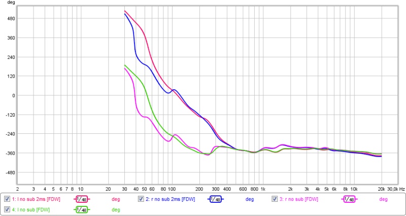
So measurements at LP with 2ms less delay on mid-tweet.
SPL

Phase

STEP

Phase and step don't look so good in comparison.
And the new wavelets without sub
left

right

"Streng maar rechtvaardig". I hope that reference is funny in Holland as well, forgot were it came from exactly.
There should be a picture of the speakers and the listening position a few pages back (scrubbed clean for X 🙂 ) The left speaker is near a wall and window, the right one is in the middle of the room.
And yes, it's going a bit fast 😛
So measurements at LP with 2ms less delay on mid-tweet.
SPL
Phase
STEP
Phase and step don't look so good in comparison.
And the new wavelets without sub
left
right
"Streng maar rechtvaardig" Yes, that works 😀
(it's Dutch alright)
You're right, this delay isn't the answer. Judging the phase response without it all it needs is a tiny bit of help straightening out that phase bump, without an overall delay change.
Or... you could try 1 ms less, which should bring you somewhere in the middle. It did remove more of that dip. (slightly less than one ms seems to be needed).
Measurements with 0.8ms less delay on mid tweet.


left

right

This also doesn't seem to do the trick (or something went wrong with the measurements, it looks really weird). I have to start cleaning up before my GF gets home so no more measurements for today. I'm going to think a bit about all these results, no way I understand the total implications of it all at the moment.
left
right
This also doesn't seem to do the trick (or something went wrong with the measurements, it looks really weird). I have to start cleaning up before my GF gets home so no more measurements for today. I'm going to think a bit about all these results, no way I understand the total implications of it all at the moment.
I have to start cleaning up before my GF gets home so no more measurements for today. I'm going to think a bit about all these results, no way I understand the total implications of it all at the moment.
I know how the cleaning up part feels! 😛
You have some things or ideas to play with. Without the delay we're pretty close. A little FIR clean-up might help there. Both phase and FR. No idea how your current crossover filters are build up, some pretty small changes could align it all. It's been interesting!
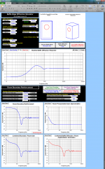
Would be curious if example Jeff Bagsby tool below can predict and confirm whats going on or maybe use room simulation menu in REW, below settings is pure guesswork regarding dimensions but as seen in REW plot room does move mountains to a perfect flat 20Hz-20kHz bandpass at listening position.
Attachments
So I got APL_TDA working on the laptop but since I can't save files with the demo I'm gonna need some specific requests for graphs you'd like to see.
@ BYRTT the tool doesn't work with open versions of office and I don't have excell. I'll take a look at the REW room thingy.
@ BYRTT the tool doesn't work with open versions of office and I don't have excell. I'll take a look at the REW room thingy.


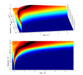
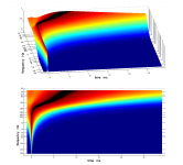
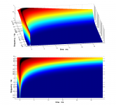
2d views for the measurements:
right with sub

left with sub

right no sub

left no sub

These were all taken at the listening position, the basscabs were turned upside down. The crossover used is the 1m linear phase crossover for the basscabs normal (close driver spacing).
right with sub
left with sub
right no sub
left no sub
These were all taken at the listening position, the basscabs were turned upside down. The crossover used is the 1m linear phase crossover for the basscabs normal (close driver spacing).
Last edited:
I played around with the REW room mode simulator.

Doesn't seem to be very usefull for what I'm trying to do.
Doesn't seem to be very usefull for what I'm trying to do.
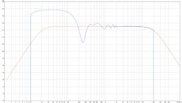
In APL_TDA plots are at listening position think they look relative good, another thing is does APL_TDA show clean response and timing if you hardwire loop your system boxes. Looks like room collapse ala brickwall below about 180Hz so subs will never have a chance to integrate good.
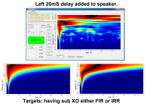
Know you have FIR power but not sure if taps available at all XO points and it makes a difference how plots suppose to look. First below is (targetcurves) perfect IR example of FIR XO points all the ways for IRR pass-band domain 15Hz-22kHz. Second is same but with one IRR 4th order 50Hz subwoofer XO point, and third is IRR 4th order XO points all over 50hz/300Hz/2500Hz.
Know you have FIR power but not sure if taps available at all XO points and it makes a difference how plots suppose to look. First below is (targetcurves) perfect IR example of FIR XO points all the ways for IRR pass-band domain 15Hz-22kHz. Second is same but with one IRR 4th order 50Hz subwoofer XO point, and third is IRR 4th order XO points all over 50hz/300Hz/2500Hz.
Attachments
Last edited:

Well, seeing the response at 300 Hz, where there used to be a dip, it looks pretty controlled there. The question is, is this a trade off from having the bass bin upside down or are we looking at some previous crossover/FIR action not working for this new way of arranging things.
That's hard to know for us, as we don't know what the crossover is exactly. All we do know is the geometry that was corrected at close distance changes when looking at it from a larger distance plus the fact that one driver has moved way further down.
Was the crossover a named one, plus FIR correction? Or was it based on acoustical measurement using whatever needed to follow a named curve. Was it corrected to follow linear phase in RePhase?
P.S. sorry for not going back trough the whole tread searching for obvious answers, we need to know where to start over from here.
It might be a good idea to get these same curves done with the bass bin in normal (upright) position. Just to see if we gained something or created a new problem or both.
Last edited:
I played around with the REW room mode simulator.
View attachment 592745
Doesn't seem to be very usefull for what I'm trying to do.
dauumn large room, at least for me!
i would move speakers to short wall
@ Manninen: That is almost the whole ground floor, not shown small income + toilet and stairway to basement + 1st floor, pics further back in this thread. I do use 2 15" woofers for sub duties for a reason 🙂. I can't use the short walls because there is either the kitchen (right) or one big window with sliding doors to the garden (left).
Also there is a big difference between optimizing sound in a living room and building a listening room. I'm doing the former 🙂.
I'm using linear phase LR4 in rephase after flattening the respons and phase of the driver in the box as measured at 1m tweeter height. (I don't do much for the woofer since it should have a pretty flat response theoretically and I can't measure very accurately below 300Hz) Rephase files attached in ZIP. Load the FIR files in Najda and adjust delays for best phase integration and STEP. 150 taps for tweet, 800 for mid and 1023 for woofer.
As far as processing power goes, I have 1023 taps per side I can add (preprocessing). I'd rather not mess with the separate driver FIR files at this point. The sub is driven by an inukeDSP so I have a lot of IIR power at my disposal for the sub. I have no idea what crossover slope or type the Denon uses, either way it can't be changed.
Measurements with basscabs normal (close driver spacing) and 4.2ms less delay on the sub. For some reason the delay was still set in the inuke.
right


Left


Also there is a big difference between optimizing sound in a living room and building a listening room. I'm doing the former 🙂.
I'm using linear phase LR4 in rephase after flattening the respons and phase of the driver in the box as measured at 1m tweeter height. (I don't do much for the woofer since it should have a pretty flat response theoretically and I can't measure very accurately below 300Hz) Rephase files attached in ZIP. Load the FIR files in Najda and adjust delays for best phase integration and STEP. 150 taps for tweet, 800 for mid and 1023 for woofer.
As far as processing power goes, I have 1023 taps per side I can add (preprocessing). I'd rather not mess with the separate driver FIR files at this point. The sub is driven by an inukeDSP so I have a lot of IIR power at my disposal for the sub. I have no idea what crossover slope or type the Denon uses, either way it can't be changed.
Measurements with basscabs normal (close driver spacing) and 4.2ms less delay on the sub. For some reason the delay was still set in the inuke.
right
Left
Attachments
Looks like room collapse ala brickwall below about 180Hz
I'm not sure I understand what exaclty you mean by this.
Measurements with about 20ms delay added to the speakers, 4,2ms less on sub and 15ms added to speakers.
Right


Left


Seeing this huge dip around the crossover point I ran some measurements with the sub phase at 180°.
basscab normal 4.2ms less delay on sub
Left


15ms extra delay on speakers


basscab normal 4.2ms less delay on sub
Left
15ms extra delay on speakers
Last edited:
I'm not sure I understand what exaclty you mean by this.....
This marked suddenly time change, at right is the one from today with midwoof baffle flipped back to normal position.
.....Measurements with about 20ms delay added to the speakers, 4,2ms less on sub and 15ms added to speakers.....
Have a look first attachment, think it looks better and better now if you bring sub even more forward so it touch the U from midwoof and we should start to see something ala one of the two targets.
Will have a look later onto your Rephase file, thought is real world acoustic slopes and correction for 9,5 inch midwood is not right probably because it so hard to get a good measurement as base for correction in this frq area.
Attachments

Last edited:
- Status
- Not open for further replies.
- Home
- Loudspeakers
- Multi-Way
- Achilles FIR 4-way