panel temperature
I have been experimenting for over a month now with a liiliput setup. All seems fine, great pictures (thanks Ace, for all the tips), happy family, so a time well spend.
One question keeps nagging. The temp of my lilliput. Think about it:
1. run a 250W bulb with an efficiency of 60%
2. light engine/fresnel efficiency of 80%
Now we have a light energy of .6*.8*250 = 120 Watts effective light trhough the panel.
3. An average movie has a luminance of 30% (what I mean is this: the major parts of a movie are relatively dark). The 70% are absorbed by the panel, laws of physic, simple as that!!!!!!!!
So, the panel gets hotter ans hotter. In my example it is exposed to 84 watts !!! Hmm, that seems to be a lot of energy for such a sensitive device.
Now the questions:
1. Can the panel handle this?
2. If not, what do you do about it?
Re: panel temperature
Heya buddy sorry for the late reply, i cool my lcd simply with a centrivical fan ( barrel fan), they cool the lcd no worries to a suficient level and more so eficiently then a normal axial fan as the barrel fans have a higher air pressure. A good lcd temp is around 30deg c, too cold and the lcd will darken, too hot and the lcd will darken also, they are meant to be run between 25 - 35deg c even though the lilliput takes upto 70deg c.
I totally agree what your saying , the darker the lcd's image is the hotter the lcd will run, thats totally true, what isnt light is otherwise heat energy, but what i am a little puzzled with is how did you get only a eficientcy rating of 60% for a hqi metal halide lamp? they should be around the 80% mark. What scale did you go by to get the 60% rating?
Trev🙂
k_o_b said:I have been experimenting for over a month now with a liiliput setup. All seems fine, great pictures (thanks Ace, for all the tips), happy family, so a time well spend.
One question keeps nagging. The temp of my lilliput. Think about it:
1. run a 250W bulb with an efficiency of 60%
2. light engine/fresnel efficiency of 80%
Now we have a light energy of .6*.8*250 = 120 Watts effective light trhough the panel.
3. An average movie has a luminance of 30% (what I mean is this: the major parts of a movie are relatively dark). The 70% are absorbed by the panel, laws of physic, simple as that!!!!!!!!
So, the panel gets hotter ans hotter. In my example it is exposed to 84 watts !!! Hmm, that seems to be a lot of energy for such a sensitive device.
Now the questions:
1. Can the panel handle this?
2. If not, what do you do about it?
Heya buddy sorry for the late reply, i cool my lcd simply with a centrivical fan ( barrel fan), they cool the lcd no worries to a suficient level and more so eficiently then a normal axial fan as the barrel fans have a higher air pressure. A good lcd temp is around 30deg c, too cold and the lcd will darken, too hot and the lcd will darken also, they are meant to be run between 25 - 35deg c even though the lilliput takes upto 70deg c.
I totally agree what your saying , the darker the lcd's image is the hotter the lcd will run, thats totally true, what isnt light is otherwise heat energy, but what i am a little puzzled with is how did you get only a eficientcy rating of 60% for a hqi metal halide lamp? they should be around the 80% mark. What scale did you go by to get the 60% rating?
Trev🙂
OK, I have some work to do on the panel cooling than.
I don't know exact figures for the effiiciency of the MHD and/or light engine, just a rough estimation. But even with these low efficiency figures is shows that the panel has to absorb quite some energy.
I think I loose a lot of light by my reflector, can't get hold of a decent one for my double ended bulb. Now I use the soupladdle type.
I measured it's relative efficiency by using a simple setup with a light dependent resistor and a multimeter (measuring the resistence over the LDR with and without the reflector -- quite helpfull when you are experimenting with your light engine since it gives you objective readings). With the reflector the resisitance is reduced by 30%, so it helps, that's for sure.
What would happen if I could get a decent reflector??? Must be much better.
k_o_b said:OK, I have some work to do on the panel cooling than.
I don't know exact figures for the effiiciency of the MHD and/or light engine, just a rough estimation. But even with these low efficiency figures is shows that the panel has to absorb quite some energy.
I think I loose a lot of light by my reflector, can't get hold of a decent one for my double ended bulb. Now I use the soupladdle type.
I measured it's relative efficiency by using a simple setup with a light dependent resistor and a multimeter (measuring the resistence over the LDR with and without the reflector -- quite helpfull when you are experimenting with your light engine since it gives you objective readings). With the reflector the resisitance is reduced by 30%, so it helps, that's for sure.
What would happen if I could get a decent reflector??? Must be much better.
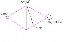
KK, lets start off with what light, reflector, frensel, condenser and panel is being used and then we will go from there.
As for a soup laddel compared to a spherical reflector, a soup laddel is brighter yess, but its very damaging to your bulb, the soup laddel fries the bulb. A soup laddel also does not direct the light realy where it needs to be and gives us a blured light efect over a pixel perfect strait through light effect with a spherical reflector, and with that being said, even a spherical reflector has its limits.
A spherical reflector can and will be brighter then a soup laddel if the lamp is at its focal, the reflector has a short focal, and if the reflector has a high quality coating. Dichloric reflector coatings are by far the most reflective coatings and also the most costly.
I have an enhanced aluminium reflector here thats very exspensive, the coating on it is so good it nearly burnt a hole in my lcd with a fan on it! For somthing thats so reflective as this reflector and to be used on a lcd, it has to be dichoric or damage will result. I have since purchased a dichloric reflector with shorter focal specs and its brighter then a soup laddel visibly, gives a pixel perfect image, and i dont fry my bulb. Also soup laddels change the colour of the light as with any other reflector will, but with a soup laddel its typically darker dropping the colour temp down to 500k or so dependant of the coating, while a dichloric reflector will raise the colour temp to a more apealing 300k, so our light not only becomes cooler, but also whiter.
Regarding frensels and having them split or not, somthing ive been asked a manny of times. Because ive been asked so much i decided to do some hands on research into the matter in the last weeks, to find out what is the best way to place our frensels. I purched 3 frensels, all have a different focal length, ring counts, i used the same lcd on all tests and the same light engine specs and optics.
In my findings frensels with a short focal, and a high ring count work best split, infact they wont work properly any other way. Frensels with a low ring count and with a long focal work best with both behind the lcd unsplit. The results are very different from one another, the short focal frensels split wer very bright split while unsplit they wer dim and light was impossible to get even across the entire lcd, also the contrast was very different.
With the longer focal frensels having them split gave us a dimmer image and the contrast looked to much as though it just ate all of our black levels away, having them unsplit gave us the right contrast level although bright scenes looked abit too bright while the dark was abit washed out, it gave an image that strained your eyes, atleast mine. So at the end of the day if you have short focal frensels with a reasonably high ring count, and have them split, we get a much brighter image then a longer focal frensel as the light is closer to the lcd, the light engine becomes very tight and more eficient, the contrast is more realisticly correct, and having the frensels split we can impliment in a keystone.
With the shorter frensels that i got a hold of, my projector is not only smaller but much brighter, infact, with all of the modds ive done on the longer focal frensels with the duel condensers ect, the shorter focal frensel is brighter alone without any duel condenser, i have since managed to just squeeze the duel condenser modd into it so you can image just how much brighter it realy is.
Another correction with split frensels is the fact some people say that the image isnt as clear as having the frensels both behind the lcd. This depends on a few things, firstly if your top frensel isnt clean sure your image wont be very clear, secondly is how far we place the top frensel from the lcd. If you have a clean frensel free from scratches, and if its flat, there is no difference in the image quality having the frensels split or not, remember we are focusing to the lcd and not the top frensel, the cleaner the top frensel is the clearer the image. Having a frensel too far from our image makes a difference too, as with having them too close. The best distance i find is 10mm with the lilliput lcd and with the copy lens, any more or any less and you will start to get crappy results.
I hope it helped you abit buddy and a few others.
Trev🙂
The results are very different from one another, the short focal frensels split wer very bright split while unsplit they wer dim and light was impossible to get even across the entire lcd, also the contrast was very different.
Hello Trev,
Good to see some hands on testing. I thought I’d add a bit more theory to you findings. I could be wrong but I’m sure you will let me know.
When the lcd is in front of the Fresnel’s with short focals, the angle that the light passing through the lcd is a greater angle than the longer focals. So the lcd would block more light, giving crappy results. The uneven lighting may be due to the outer rays having a greater angle than the rays closer to the centre. It would be interesting to find out if all lcd's preform in the same way, maybe a lcd with a greater viewing angle might give different results.
As for having a fresnal in front of the lcd, I'm still undecided if this is the best configuration just yet. I think there is a compromise happening here, placing the lcd in front sacrifices contrast/keystone and placing it behind sacrifices image. Even with the Fresnel’s clean, as you know they aren't perfect lenses and introduce “shadow aberrations”, I just made that term up hehe! A technical term for rings. This may not be a problem with the copy lens you use but I’m having a ***** of a time with mine. The triplet lenses seem to have a large depth of field and I have to have the fresnal further away from the lcd, so that the triplet doesn’t focus on the rings. The problem gets worse with keystone and lens shifting. The set up I’m currently working on is a hybrid split Fresnel with lcd in front and keystone correction, the lens shift increases the depth of field and is causing me the most grief.
DJ
Hi Trev,
I've been experimenting with fresnels as well, and got similar results.
Tried both .5 and .2 groove pitch and 34 and 20 cm FL.
I like the .2 gp with 20 cm FL best in combination with my 24cm projection triplet. One practical problem however, I have to place mu pj in the middle of my room to keep the image to a practical size.
I learned that quit some pj's operate with fresenels you supplied, what are the specs for these?
And one last question: do know where to buy usable reflectors for double ended bulbs?
kob
Dazzzla said:
Hello Trev,
Good to see some hands on testing. I thought I’d add a bit more theory to you findings. I could be wrong but I’m sure you will let me know.
When the lcd is in front of the Fresnel’s with short focals, the angle that the light passing through the lcd is a greater angle than the longer focals. So the lcd would block more light, giving crappy results. The uneven lighting may be due to the outer rays having a greater angle than the rays closer to the centre. It would be interesting to find out if all lcd's preform in the same way, maybe a lcd with a greater viewing angle might give different results.
As for having a fresnal in front of the lcd, I'm still undecided if this is the best configuration just yet. I think there is a compromise happening here, placing the lcd in front sacrifices contrast/keystone and placing it behind sacrifices image. Even with the Fresnel’s clean, as you know they aren't perfect lenses and introduce “shadow aberrations”, I just made that term up hehe! A technical term for rings. This may not be a problem with the copy lens you use but I’m having a ***** of a time with mine. The triplet lenses seem to have a large depth of field and I have to have the fresnal further away from the lcd, so that the triplet doesn’t focus on the rings. The problem gets worse with keystone and lens shifting. The set up I’m currently working on is a hybrid split Fresnel with lcd in front and keystone correction, the lens shift increases the depth of field and is causing me the most grief.
DJ
No no your right lol, have you got your frensels split? i ask cos im not sure what you mean with the lcd in front and behind, is this behind and in front of both of the frensels?
The ring problem is solvable, 10mm should be all the distance you need, atleast with the lilliput. The ring shadowing (wich is probally a better term then aberations as aberations is slightly diff) is also due to the fact of having your light rays at the incorrect angle, i learnt this the hard way
 , and also with frensels because they have rings, you will never get a perfect image, we can only acheive this if we use a pcx lens in place of the frensel with the same specs, but then you know price and wieght ect.
Pro projectors have split frensels, the grade of some of the pro projectors frensels that ive seen are crap quality, but because they have such acurate reflectors they dont have the ring problem, correct spacing also is the key as mentioned above.
Your totally right with the ray angles aswell regarding the short focal frensels, i think the polarisers on the outer part of the lcd have the light going to them on too much of an angle to yeald the same bightness as the center, so realy its just chewing our light on the sides and adding heat in those areas aswell as giving us an uneven image.
Ive noticed in this new one im doing with the short focal frensels that all of the light engine optics has to be so much closer together, for instance, the primary condenser is 1mm away from the bulb where as before it could be as far as 15mm. In the new model things have gotten a whole lot more sensitive too, everything has to be perfectly acurate to yeild perfect results, ive also had to split the condensers off with one being fixed in the light box, and the other being fixed into the lcd unit, that was totally designed because of size restrictions. One funny thing ill metion is, is in a certain test sequence modd i did the condenser would fry, in the same sequence but with the condenser nearly on the bulb the condenser is fine, strange, but ive prety much worked it out that the aluminium material around the condenser holding it, added too much heat to the outside of the condenser as light was hitting the metal, so therefor it would fry, now the light only goes through the condenser and it seems fine so that has to be it, a little somthing for future designing to keep in mind. Ive just started on the lcd unit today so lets just cross our fingers it turns out spot on with the keystone, ive done enough drawing on it lol.
Trev🙂
k_o_b said:Hi Trev,
I've been experimenting with fresnels as well, and got similar results.
Tried both .5 and .2 groove pitch and 34 and 20 cm FL.
I like the .2 gp with 20 cm FL best in combination with my 24cm projection triplet. One practical problem however, I have to place mu pj in the middle of my room to keep the image to a practical size.
I learned that quit some pj's operate with fresenels you supplied, what are the specs for these?
And one last question: do know where to buy usable reflectors for double ended bulbs?
kob
Heya Kob, yeah thats a problem with having a shorter focal projection lens, we are lucky in a way that the 7inch lcd is just 7inches or that lens wouldnt be usable in the way of the screen size fitting through the lens, and in the way of the projection size. Try to get a negative pcv lens and that should lengthen the focal on the copy lens, if thats no good you could always open one up and space the optics apart slightly, that would do the trick though it may also cut down your feild of veiw. As soon as ive got some time ill open one up and see what modds we can do on that lens. You could also try a longer focal top frensel, that should make a difference if you can manage to fit the image in it.
Regarding parts, ive hit you with an email.
Trev🙂
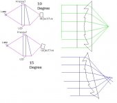
The following info might help in understanding what I'm trying to achieve.
Here is a pic of a standard split fresnel set up. Take note of the light running parallel to the fresnel grooves. This is the most efficient way to run it.
There are two problems when the fresnel is tilted to correct for keystone. The first is that the grooves are no longer running parallel with the light, it is blocking it, causing a shadow. The second is that Spherical aberration is introduced into the objective. You can clearly see this in that the rays are no longer focused to a tight point. Because the fresnel is in front of the LCD, it is now part of the objective and any distortions it introduces will be visible. This is the reason why we can only get 10 degrees of keystone correction, any more tilt and the edges of the LCD distort and/or blur.
We can gain an extra 5 degrees of correction by tilting the fresnel 15 degrees and tilting the objective in the opposite direction. This is called Scheirmpflug rule or lens shift.
Attachments
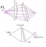
The next method of keystone correction is where I hold my hope. I haven’t fully tested it yet as I’m waiting on a FFC but I have tested it with clear OHP sheets and it all works correctly. I have actually achieved more than 15 degrees of correction. The only thing that will let this method down would be if the LCD’s contrast weren’t consistent over the screen. The Samsung I will be using is relatively new with a large viewing angle, so fingers crossed. Here is a pic, the objective can nearly be level with the top of the screen at about 2400mm.
Attachments
Because I’m using a 17’ LCD the Fresnel’s have to be large so here is an alternative. It’s a compromise but I think with some fine-tuning I should be able to get it to work. If you look at the ray trace I deliberately raised and placed the lamp closer to the rear fresnel to spread the light slightly to compensate for the ring shadow in the second fresnel. As an added bonus this config actually improves Spherical aberration.
What did you do to fix it?
DJ
now the light only goes through the condenser and it seems fine so that has to be it,
What did you do to fix it?
DJ
Attachments
heya dazzla, hmmm i dont know where you got some of those drawings from but they dont look too right, tilting the lcd ones do but the frensesl ones arnt too correct.
The light that goes along a axis wont change its axis from a lens, only a prisim or a mirror can change the axis, and thats what give us lens shift, maybe you mixed that up with keystone, who knows but however with a top frensel tilted it wont alter the lights axial path, what it does alter is the magnifacation and thats what gives us the keystone.
The reason for the rings as ive stated in an earlier post is from the light traveling in a single given direction, if you could change the light rays to match the angle on the rings of the top frensel then you wouldnt get the ring shadow, although not impossible, in our diy world it is on the cheap, and honestly i wouldnt be too fussed about it.
A rule of thumb to follow is to always have the lcd panel perpendicular to the lcd, thats a must, i saw a drawing in there that wont work as it was out of paralelle.
Trev
A small notice, for anyone who has emailed me in the last 2 weeks and wonderd why i havnt replied, is because my email has currently screwed up and all of them are gone, i have changed my email addy since, so those who would like to email me back feel free.
Trev🙂
Trev🙂
heya dazzla, hmmm i dont know where you got some of those drawings from but they dont look too right, tilting the lcd ones do but the frensesl ones arnt too correct.
I drew them, what do ya mean not, to, correct😡 😡😡
Just joking and you’re correct they are not 100%. The software I used is meant for drawing house plans so it's a real pain to use for ray traces. The rear fresnel is right out of wack, I rushed it hoping you wouldn't notice, Bugga.
A rule of thumb to follow is to always have the lcd panel perpendicular to the lcd, thats a must, i saw a drawing in there that wont work as it was out of paralelle.
If you mean the LCD and lens, then I have to disagree. Tilting the lens with regards to the lcd will compensate for spherical aberration intoduced by the tilted second fresnel.
DJ
Ace - plans for sale yet?
I've been away from the boards for awhile, so I don't know the latest developments, but are your plans available for sale yet?
I've been away from the boards for awhile, so I don't know the latest developments, but are your plans available for sale yet?
With a lcd of 381mm and fresnel fl of 220mm, the beam angle required by the fresnel would be about 81 degrees and the angle of incidence would be half this, 40.5 degrees. When light strikes a lens it can do two main things, refract or reflect. The thing that determines how much reflection and how much refraction that will occur, is called the angle of incidence. As the angle of incidence becomes bigger, more light is reflected and less refracted until a point is reached where total reflection takes over, this is called the critical angle and its value is about 41 degrees. So in this situation you’re at about the most efficient position without using a condenser. Condensers a good for improving the situation when the fresnel fl is larger than half the its dimensions, as in Ace’s setup.
I have to make a correction to a post I made a few pages back. Most of it is correct exept for the part about total reflection and critical angles. This only acures when the light leaves a high density material to a low density one, in other words when it leaves a lens as opposed to entering it.
oops sorry😱
DJ
I know this has been posted before but are the plans available ACE? Really wish to start my new project.
botcolon
botcolon
I know this has been posted before but are the plans available ACE? Really wish to start my new project.
Heya buddy, put it this way, they are done in a way lol, they are done on paper but not on the comp, i just have to draw them on the comp and then their done, ( not all just the lcd unit), the guide will be in a forum im making up some time this week, the drawing wont take long to do its just a matter of free time on my behalf, i want to get you guys going asap, like now! but ive had a real lack of time in the last month, work is catching upto me😕.
Im going to try and get the waiting lot of you guys going altogether in the one hit, so atleast that way i can show you what to do as you go along all together, to make it a breaze for you guys to construct it. Ill have the forum up before the plans with guides telling you how to bend the alloy so you can get some practise in before the comming days of the plans, about 2 days or so beforehand.
Trev🙂
EDIT along with the materials list
ace3000_1 said:
Heya buddy, put it this way, they are done in a way lol, they are done on paper but not on the comp, i just have to draw them on the comp and then their done, ( not all just the lcd unit), the guide will be in a forum im making up some time this week, the drawing wont take long to do its just a matter of free time on my behalf, i want to get you guys going asap, like now! but ive had a real lack of time in the last month, work is catching upto me😕.
Im going to try and get the waiting lot of you guys going altogether in the one hit, so atleast that way i can show you what to do as you go along all together, to make it a breaze for you guys to construct it. Ill have the forum up before the plans with guides telling you how to bend the alloy so you can get some practise in before the comming days of the plans, about 2 days or so beforehand.
Trev🙂
EDIT along with the materials list
should I buy my 7" xga lilliput now then? its AUD299 + AUD50 postage. I assume I will need to pay oz import duty (10% isn't it?)
in anticipation...botcolon
- Status
- Not open for further replies.
- Home
- General Interest
- Everything Else
- The Moving Image
- DIY Projectors
- Ace_3000....pictures of Projector?