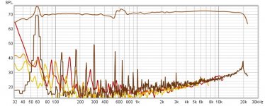
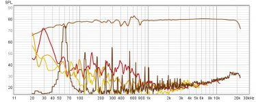
This is the full fr of the piezo accelerometer on the dunlavy side panel. The 60hz mains AC line interference is terrible, but as far as normal, braced cabinet resonances are concerned, totally irrelevant, and can be windowed out, so for all intents and purposes, measurements from 70 hz and up are unaffected by any noise that's left in the system, and can be counted on as reliable.
Attachments
Last edited:
Thanks! What are we seeing on the lower, jagged plots? Is that the same thing with different smoothing? Or harmonics? Although the noise is mostly a good way down, I wonder if those spikes at 540, 660 and 880 are contributing to your cabinet measurement? That said, the spike at 300 does not seem to be contributing.
It will be interesting to see what your shielding does. Will you have to shield both sides?
It will be interesting to see what your shielding does. Will you have to shield both sides?
Dunlavy panel resonance vs "acoustic null technique" panel resonance. The reason I'm spending time on this is for measurement verification. I'm pretty satisfied with the results I'm getting.
Attachments
Last edited:
The traces areThanks! What are we seeing on the lower, jagged plots? Is that the same thing with different smoothing? Or harmonics? Although the noise is mostly a good way down, I wonder if those spikes at 540, 660 and 880 are contributing to your cabinet measurement? That said, the spike at 300 does not seem to be contributing.
It will be interesting to see what your shielding does. Will you have to shield both sides?
Brown- noise
Red- 2nd harmonic
Yellow- 3rd harmonic
In this plot, the signal wasn't high enough(To early
") ), so some noise spikes did get through. When I raise it up, they disappear from the trace. I guess that means they're not coming from the buffer itself, but from outside the system.
), so some noise spikes did get through. When I raise it up, they disappear from the trace. I guess that means they're not coming from the buffer itself, but from outside the system.As far as the shielding goes, yes, I will sandwich the wiring between the panels.
Last edited:
I just spoke with my wife, who is a retired electro magnetics (EMI/EMC) engineer, who spent 30 years running an EMI lab...
She recommends the easiest/cheapest way to shield the cabling is to twist the wires together (from transducer to preamp), then wrap the wire bundle in aluminum foil, and ground the aluminum foil shield at the preamp...
This is assuming you still have some noise issues.
She recommends the easiest/cheapest way to shield the cabling is to twist the wires together (from transducer to preamp), then wrap the wire bundle in aluminum foil, and ground the aluminum foil shield at the preamp...
This is assuming you still have some noise issues.
hifijim
So cool! What a great resource! Thanks!
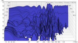
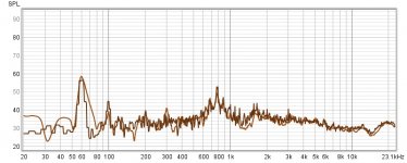
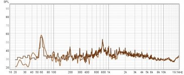
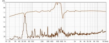
Here is a small signal vs noise plot and a large signal vs noise plot. As you can see, the spikes stay at the same level in both plots, so it definately is coming from emi. Hd below 60Hz also stays at the same level regardless of signal, so that's also coming from outside the system. The CSD graph is of the Dunlavy panel with a very large signal input. The situation gets very chaotic compared to the smaller signal shown earlier.
So cool! What a great resource! Thanks!
Here is a small signal vs noise plot and a large signal vs noise plot. As you can see, the spikes stay at the same level in both plots, so it definately is coming from emi. Hd below 60Hz also stays at the same level regardless of signal, so that's also coming from outside the system. The CSD graph is of the Dunlavy panel with a very large signal input. The situation gets very chaotic compared to the smaller signal shown earlier.
Attachments
Last edited:
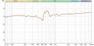
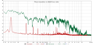
Thanks for the explanation of the graphs. As a point of comparison, here is my Piezo pickup into 1M with silence and with a little B&W HT speaker playing pink noise at 84dB 1M.
Despite the mains noise seen in the baseline, I'm still getting about 45dB S/N across the midrange. ARTA agrees with this graph. On the REW graph the -20dB line actually represents -120dBfs If I can come up with some shielding next week, maybe the S/N can be improved.
Despite the mains noise seen in the baseline, I'm still getting about 45dB S/N across the midrange. ARTA agrees with this graph. On the REW graph the -20dB line actually represents -120dBfs If I can come up with some shielding next week, maybe the S/N can be improved.
Attachments
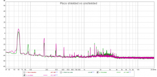
And here is a comparison of piezo pickup unshielded and then covered with a patch of aluminum foil that is grounded to the system. It's a mixed bag, for sure. While there is significant reduction for some mains harmonics, others are much higher with the shield. As is the hash around 2K. Maybe a better grounding point would help?
Attachments
hifijim
Okay, I did everything here that your wife recomended and it dropped all the emi spikes a huge amount! Wow, that works! Looks like around 15db across the board! I deleted the hd on the first graph to clarify the noise reduction
Okay, I did everything here that your wife recomended and it dropped all the emi spikes a huge amount! Wow, that works! Looks like around 15db across the board! I deleted the hd on the first graph to clarify the noise reduction
Attachments


Last edited:
On this graph, I shielded other exposed wires that I should have shielded the first time around. Now it's about 18db down from the above graph. I checked hd, and it is below the noise floor, so I left it out. Noise is definitely no longer a problem. Tell your wife I said thank you, Jim!
. Tell your wife I said thank you, Jim!Attachments
Now that everything is good, here's another concrete slab floor measurement(First graph) with the normal mic reading at 100db at the piezo. The signal is buried in the noise floor, which begs the next question, which is on the second graph..
Why is there any signal above the noise floor on the panel measurements where there is no apparent vibration? For example, look at the response from 2khz and up. Is there actually a perfectly flat response being picked up on the panel, all the way up to 20 khz? Impossible! so why is it reading that way compared to being taped to the floor? Anyone have an answer? It would seem to me that anywhere there was no vibration would be buried in the noise floor, like when it's actually taped to the floor. It's tripping me out, actually. Maybe I'm doing something wrong, or just looking at it the wrong way.
Why is there any signal above the noise floor on the panel measurements where there is no apparent vibration? For example, look at the response from 2khz and up. Is there actually a perfectly flat response being picked up on the panel, all the way up to 20 khz? Impossible! so why is it reading that way compared to being taped to the floor? Anyone have an answer? It would seem to me that anywhere there was no vibration would be buried in the noise floor, like when it's actually taped to the floor. It's tripping me out, actually
. Maybe I'm doing something wrong, or just looking at it the wrong way.Attachments
Last edited:
Pertaining to the above question, could the piezo somehow be "grounding" itself out while being taped to the floor? That is the only thing that would make any sense. Nope, Just tested it on a brick sitting on rubber and no signal transmitted at an acoustic 100db at the piezo.
Last edited:
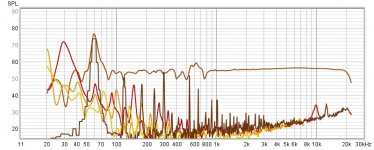
The next graph is also strange. I placed a small piece of 1/8" thick, adhesive sorbothane between the cabinet and the accelerometer, and compared to none, all else being equal. As you would expect, it killed the resonance at 650hz, and then some. But what you would not expect is on the other parts of the spectrum, where there were no resonances at all. Huh?
(I do have to admit, there are smaller resonances not being transmitted through the sorbothane also, but why does the amplitude(for lack of a better word), go up where there are no huge resonances?
(I do have to admit, there are smaller resonances not being transmitted through the sorbothane also, but why does the amplitude(for lack of a better word), go up where there are no huge resonances?
Attachments
Last edited:
The next graph is also strange... ... But what you would not expect is on the other parts of the spectrum, where there were no resonances at all. Huh?
Nothing surprises me when it comes to measuring vibration responses in structures. It is a very complex system, and some of the influential parameters are difficult to control or quantify.
Just a thought, but the sorbathane is not an ideal damper... it has mass, stiffness, and damping. It may be acting as a spring at many frequencies, and only at the cabinet resonance is there enough wall movement for the damping to have an impact. I don't know what is happening, but this is one plausible explanation.
I agree. Sorbothane needs to be compressed to actually work. No compression, no damping. The tape is probably giving just enough pressure to kill the main resonance, but not enough to make it kick in at the other frequencies, where it is probably acting like a spring.
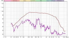
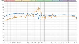
The more accelerometer measurements I take though, the more I'm realizing just how limited this method is compared to the null method, which actually gives you an acoustic measurement of the side panel as a whole as apposed to one mechanical resonance measurement in one tiny spot on the baffle, which changes pretty drastically in every different spot you measure, and on top of that, it tells you nothing about whether it's being transmitted to the air or not, or how loudly, relative to what's coming out of the front of the speaker.
The graph below actually shows the acoustic side panel measurement plus relative loudness compared to the front of the speaker at the same distance. How can an accelerometer compete with that? An accelerometer does have it's uses, but it's more academic in nature.
Attachments

Last edited:
The next measurement I make will be like the one above, with the same speaker, but this time at the full listening distance of 2 meters instead of 12". It will be interesting to see how the response relationships change over that distance. All I know, is that the last time I did this null test using correlated pink noise, I could hear it from anywhere in the house.
Last edited:
Are you forgetting that I have already shown that? I know it was a few pages ago, but it did.The graph below actually shows the acoustic side panel measurement plus relative loudness compared to the front of the speaker at the same distance. How can an accelerometer compete with that? An accelerometer does have it's uses, but it's more academic in nature.
A contact mic, or an accelerometer can more easily than a normal mic, pinpoint vibration points on a surface. That can be very useful if you want to know where bracing might be needed, or be most effective.- Home
- Loudspeakers
- Multi-Way
- Accelerometers to measure panel vibrations?