Behringer | Product | ADI21
This is what I bought for the tape accelerometer buffer. 5m ohms and a pure bypass mode. $35
This will be plugged into a usb a/d converter and will stay in the digital domain until it reaches the digital crossover outputs.
This is what I bought for the tape accelerometer buffer. 5m ohms and a pure bypass mode. $35
This will be plugged into a usb a/d converter and will stay in the digital domain until it reaches the digital crossover outputs.
Last edited:
Very cool, and made for exactly what you want to do. Just don't get carried away with tube emulation for your measurements. 😀
Pano
That’s funny!
I read that 10m ohms will get the piezo flat down to about 30hz, so I’m assuming 5m is probably flat down to around 50hz, way better than what I need it for.
That’s funny!
I read that 10m ohms will get the piezo flat down to about 30hz, so I’m assuming 5m is probably flat down to around 50hz, way better than what I need it for.
That's good. At 1M my piezo does OK, better than it does at 500K. Still needs EQ, tho.
I stuck a pair on my dishwasher and made a recording, worked well. Also on the air conditioner, but that was less interesting.
I stuck a pair on my dishwasher and made a recording, worked well. Also on the air conditioner, but that was less interesting.
Just found this documentation. 10m ohms is recommended and 1m is the minimum, so 5m should be just fine
https://www.te.com/commerce/Documen...DS_DT_Series_without_Leads_A1.pdfCAT-PFS0004
https://www.te.com/commerce/Documen...DS_DT_Series_without_Leads_A1.pdfCAT-PFS0004
Last edited:
One of the first things I'm going to attempt with this accelerometer/buffer setup, is to emulate Atkinson's accelerometer results from what he performed on the Dunlavy's. If it's very similar, I'll know I'm on the right path.
Last edited:
I'm sure some have read this article, and some have not. Fascinating.
The Sound of Surprise (the loudspeaker/stand interface) | Stereophile.com
The Sound of Surprise (the loudspeaker/stand interface) | Stereophile.com
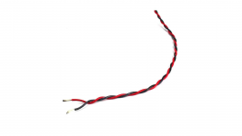
Delicate operation. Solder at the lowest possible temperature. The plastic will melt at the slightest provocation. I bought two, just in case I flubbed up on one, which I may have🙂. You can see some warping of the plastic on one. Each wire is terminated with an alligator clip on the opposite end. These things are tiny!
Attachments
Last edited:
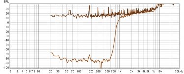
First measurement of signal vs noise floor with piezo accelerometer attached to concrete floor. Excellent results! This means that the piezo is picking up zero sound through the most important frequency band(110db measured at the piezo with calibrated mic). The drop in signal below 600hz is due to the huge impedance mismatch that will be fixed later on today when I get the buffer amp. When that is fixed, the signal should be perfectly flat with the noise floor(while attached to the concrete floor), down to around 50hz.
Attachments
Last edited:
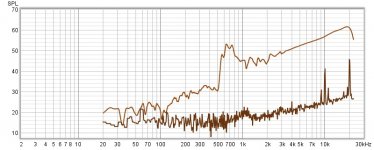
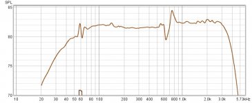
Dunlavy panel vs noise floor. Taking the impedance mismatch into consideration, the accelerometer response looks extremely linear, and the panel resonance on the Dunlavy is sticking out like a sore thumb, exactly where John Atkinson measured it at. When the buffer gets applied, the signal won't have the downward trend that it does now. Things are looking good! These piezo accelerometers must have extraordinarily high source impedance, even compared to piezo contact mics.
Attachments
Last edited:
The noise floor will be much higher with the buffer in line. The noise measurements above are purely electronic in nature, and not acoustic in any way.
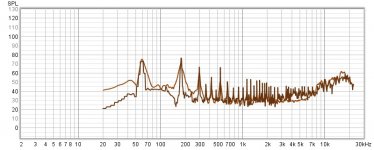
Okay, this is the first accelerometer measurement with the buffer. In this measurement, accelerometer is taped to the concrete floor. Exactly as I hoped, the signal is buried in the buffer's electronic noise floor. That means it's not picking up any audio signals through the air. Noise is pretty bad though.
Attachments
Last edited:
Dunlavy accelerometer measurement. It's interesting how that one point on the exact center of the side panel is effecting the accelerometer, which does not represent the overall acoustic output of the panel as a whole. Ignore the blip at 60hz. It's a result of noise.
It's pretty obvious why they didn't publish the thd and noise spec.🙂 And yes, it is in bypass mode.
It's pretty obvious why they didn't publish the thd and noise spec.🙂 And yes, it is in bypass mode.
Attachments
Last edited:
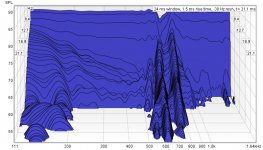
Thanks for the graphs! Looks like good progress on these.  You can certainly see the vibration spike.
Have you tried a baseline measurement with the film mic taped to your speaker, but with no sounds? What's the S/N ratio? At 5M unbalanced, electrical noise is going to be a problem, but maybe the vibration signal is strong enough to drown the noise. You might be able to shield them with aluminum foil connected to a ground point. Or it could make things worse, that has happened to me.
Looking forward to seeing more.
You can certainly see the vibration spike.Have you tried a baseline measurement with the film mic taped to your speaker, but with no sounds? What's the S/N ratio? At 5M unbalanced, electrical noise is going to be a problem, but maybe the vibration signal is strong enough to drown the noise. You might be able to shield them with aluminum foil connected to a ground point. Or it could make things worse, that has happened to me.
Looking forward to seeing more.
I need all the help I can get, thanks. I’m definitely out of my element with this piezo accelerometer business.
I did a bit of reading a couple weeks back and there was talk of needing shielding for these. But if silent vs vibration is a high enough ratio, then maybe electrical shielding doesn't matter.
Some of what I read talked about taping these to the panel with a piece of paper over them. Is that what you did, or just straight tape? Asking because maybe grounded foil over the mic could help.
Some of what I read talked about taping these to the panel with a piece of paper over them. Is that what you did, or just straight tape? Asking because maybe grounded foil over the mic could help.
In post 173 you measured a substantial cabinet radiation from 600 - 750 Hz using the cancellation null technique. Your accelerometer data agrees with that. It's nice when data agrees with data... conflicting data is painfully annoying...
J.
J.
I have an idea that may work. A 2 foot x 4 foot sheet of stainless steel, several mm thick that can be placed between the offending sources and the piezo/unshielded wire setup. I actually have two of these sheets. It might be an interesting experiment to try. I'll do it today. I can try grounding these panels too.
Last edited:
- Home
- Loudspeakers
- Multi-Way
- Accelerometers to measure panel vibrations?