Hi Rafa. Unfortunately we had to close the pre-order early. We use only genuine parts from quality US suppliers. They only have so many parts in stock and we are going to have to wait for them to restock. We're waiting to hear back. More information here: Amp Camp Amp Kit V1.6 - Pre-Order Status Page – diyAudio Store
Jason,
Thanks for all you do and putting up with us Greedy Boyz!
Luckily I ordered in time (actually the 1st hour the ACA preorder page was up). But I am curious...how many orders are projected to ship on 7/31/18, if you don't mind?
Best,
Anand.
This guide uses the 19V supplies, so I set 10V.
If you have 24V supplies, set 12V.
😀
Hello, I remember reading somewhere that if I use the new 24V/5A PS for the V1.6 on my V1.5, I could boost the output from 5W to 6W. From you post, now I believe I will also have to set the voltage to 12 V. Would you know why the version 1.6 kit could do 8 W, what else is different between the two versions aside from the 19 V vs 24 V power supplies?
Also, I have an old laptop (Dell I think) power supply that is 24 V/4.7 A, do you think I can just it, instead of having to buy the new 24 V one from the DIY store?
I think your laptop supply will be fine. Just make sure the plug's polarity is
what the amp expects.
If you use a 24V supply, you should make the '12V' adjustment.
Can't comment about the 8W. Perhaps it's quoted at a different distortion figure
from before?
what the amp expects.
If you use a 24V supply, you should make the '12V' adjustment.
Can't comment about the 8W. Perhaps it's quoted at a different distortion figure
from before?
Dennis - good catch on the polarity - I managed to blow a pretty good sized hole in a Tripath chip a year or so ago by "ugrading" to a supply from a pair of old Monsoon speakers that was wired the other way. My bad for not checking, of course.
I think your laptop supply will be fine. Just make sure the plug's polarity is
what the amp expects.
If you use a 24V supply, you should make the '12V' adjustment.
Can't comment about the 8W. Perhaps it's quoted at a different distortion figure
from before?
Thank you very much. Another question, the guide shows the two channels not layout in mirror image, any particular reason why I cannot lay them out such that the 3300 uf caps will be on the same side? That is, near the back panel side.
Finally got it done today! Set to approx. 10 V cold, it's getting late and I wanted to try it out right away so I'll re-do it tomorrow. For now, it sounds good, but there is a thump every time I turned it off, and I turned it off first. It's not too loud but loud enough to have me concerned. I wonder if I did something wrong, or this is normal for this amp?
1) What is the output impedance of this amp (below 1khz), for the lower gain (10dB), higher feedback option?
2a) In the bridged monoblock version, I take it that the overall gain using two of the 10dB versions strapped together is 16dB? And the overall gain using two of the 14dB versions is 20dB?
2b) How does the output impedance change in the bridged monoblock version? Assume XLR inputs with a true balanced source.
The DF is 10 into 8, which is .8 ohms.
This becomes 1.6 ohms (DF=5) in balanced or bridged mode.
The gain remains the same - it's relative to the sum of input signals.
The DF is 10 into 8, which is .8 ohms.
This becomes 1.6 ohms (DF=5) in balanced or bridged mode.
The gain remains the same - it's relative to the sum of input signals.
Ah!
Nothing is for free.
Thanks Mr. Pass!
Best,
Anand.
Excellent 6L6. Your interesting and informative thread is being followed by members of the Klipsch forum. We’re always looking for clean amps to power efficient speakers.
Last edited:
When assembling or installing anything such as a water pump on a car you install all bolts, screws, in before tightening any of them. If you don't some will not go in correctly.
I can hear my late father telling that to me as I tell it to my son’s.
DizRotus - Thank you! This is a great amp, I'm sure you will hear glowing reports from your members who build it. 🙂
Look into the M2x when it becomes available, it's next on the list of the instant classics. (And, of course, the Aleph J...)
Look into the M2x when it becomes available, it's next on the list of the instant classics. (And, of course, the Aleph J...)
The amp really sounds good so far, but very hot. So I placed an little fan on top to suck the hot air out and it worked great.
Hi, everyone! I’ve been looking forward to this build for a LONG time..! Finally sat down to do it today.
Everything went together smoothly but I had a little snafu, not sure where to start looking.
One channel works great and biased easily to 12v (I have the 24v power supply).
The other channel won’t bias more than 200mv. I’m getting 24v to the board, but as I trace around and compare values to the known good board I find a voltage discrepancy; measuring one leg of R7 gives me 24v as it should, but the other leg shows 5.5v vs 16.93v on the known good channel.
I’ve never worked with transitstors before, so I’m not sure what this means, but something I noticed was Q4 on the bad board shows 24v on both outside legs. I checked it with a diode tester and from the middle leg to the outside leg I get no readings. This is different from Q4 on the good board. This is measured on the board, though, I didn’t think to measure it before starting... so I’m not sure if that measurement is valid, or a red herring.
Thoughts on where to look or what to check appreciated!
I would start looking for the "error" on R7. It seems the current through R7 is much higher on the bad unit. This would probably result it wrong DC working condition for Q4. Maybe Q3 is drawing to much current? …..are the resistor values correct around the Q3?
Has C2 correct polarization…...if not it will probably "leak"?
I am not an expert…...but just trying to use logic…….
Has C2 correct polarization…...if not it will probably "leak"?
I am not an expert…...but just trying to use logic…….
Thank you for the ideas!
Resistors are all correct values. All caps are correct in terms of polarization. Thoughts on anything else to check?
Resistors are all correct values. All caps are correct in terms of polarization. Thoughts on anything else to check?
What is the voltage over C2?
Voltage on base of Q2 could also be interesting to measure. This could tell if Q2 has wrong DC characteristic and is constant "on". Check the soldering for shorts at Q2 pins. Something indicates that C2 is shorted by Q3 since you only have 5.5 V at the Q2 Collector ("other" end of R7). Q3 could also be damaged…..so it is shorted.
Voltage on base of Q2 could also be interesting to measure. This could tell if Q2 has wrong DC characteristic and is constant "on". Check the soldering for shorts at Q2 pins. Something indicates that C2 is shorted by Q3 since you only have 5.5 V at the Q2 Collector ("other" end of R7). Q3 could also be damaged…..so it is shorted.
Non-functioning 24V power supply.
I ordered and received the 24V power supply for ACA 1.5.
Last night I plugged it in and started to reset the bias to 12V.
First of all I had to unplug and replug it several times before it made a good connection and powered up the amp. Then in the midst of setting the bias on the second channel it quit completely.
The blue light is on. I stuck one probe from my multimeter down the center of the plug and the other on the outside. No voltage. (In contrast the old power supply returns a reading of 19.61 volts.)
I will report this problem to contact@diyaudiostore.com. Anyone else have this problem?
-Tom-
Hi Tom,
We'll reply to you in the email helpdesk and debug. The fact you had to plug and unplug it a few times suggests maybe a problem with the DC jack or a short. These come with a 3 year warranty so if it was defective we'll get you a replacement.
We'll reply to you in the email helpdesk and debug. The fact you had to plug and unplug it a few times suggests maybe a problem with the DC jack or a short. These come with a 3 year warranty so if it was defective we'll get you a replacement.
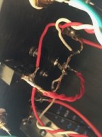
Not the Power Supply, the Input Jack
I had a problem when I plugged in the new Meanwell 24V power supply. It took several tries to get a connection, and then when I was moving the case around while adjusting the bias, it quit altogether, although the original 19V power supply continued to work.
It appears to be an inconsistent connection in the power input jack. The original power supply made a better connection than the Meanwell, but now that I have fooled with it, neither work! Both will flash the pilot lights briefly as you slide the plug in, but a good connection cannot be made at any position of the plug.
Bother!
Any ideas on how to approach this? The solder connections to the input jack all look good, and no wires appear to be touching (see photos).
-Tom-
PS: The reason the voltage did not register originally for the Meanwell was that I had the multimeter set on 20V, not 200! Doh!
Attachments

- Status
- Not open for further replies.
- Home
- Amplifiers
- Pass Labs
- ACA V1.5 Illustrated Build Guide