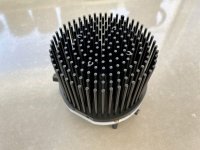
All I did was buy a similar looking heatsink (sales link in post #34 of this thread), and wait for it to arrive from China. When it was delivered, I simply measured its dimensions and drill-hole pattern with a cheap digital caliper. Then I laid out my custom PCB to match that heatsink. A typical and standard DIY approach. I included plenty of slack & slop in my mounting holes, just in case the super low cost heatsink wasn't machined with the same precision we've grown accustomed to from high quality suppliers like ModuShop / HiFi2000.
The PCB fab house calculates their price, based on the size of the rectangular bounding box they extract from my Gerber files. Their software says my Gerbers (circular board) are enclosed by a 120mm x 115 mm rectangle. Which seems correct to me.
The PCB fab house calculates their price, based on the size of the rectangular bounding box they extract from my Gerber files. Their software says my Gerbers (circular board) are enclosed by a 120mm x 115 mm rectangle. Which seems correct to me.
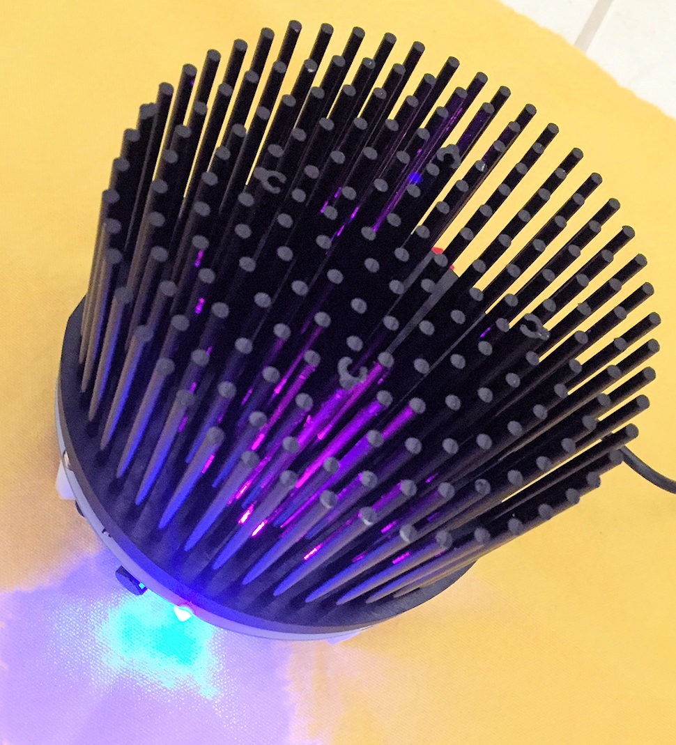
ACA with J112 and a SMPS filter built-in? AND a place to put a couple of nifty LEDs to make the heatsink glow a little? This is awesome! 
Seriously, I love the way this looks!
Seriously, I love the way this looks!

Mark, if you don't mind me asking, how much did the whole kit cost you to put together?Shipping out complete parts-kits to builder/listener pals who volunteered to be guinea pigs. Let's hope they are delighted.
_
Daniel
No idea. I bought stuff with wild abandon and in a big hurry. A large amount of it (e.g. M5 threaded speaker posts) turned out not to be usable. Bought from Ali Express, eBay, Amazon, Mouser, DigiKey. "Bought" from my own storeroom of components. Maybe some day it'll become important to calculate a total cost figure, but there are a few hurdles to clear first.
Hi Mark,Shipping out complete parts-kits to builder/listener pals who volunteered to be guinea pigs. Let's hope they are delighted.
_
I wasn’t aware you were looking for volunteered to be guinea pigs...looks like I have missed a nice opportunity.
To the lucky ones, have fun building🙂
Eric
Called Friend_A on the phone and asked, "Which two people should I call, who might volunteer to build these four porcipine amp-channels, and evaluate their sound?"
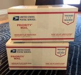
Friend_A said "ME!! Me and MutualFriend_B". 3 minutes later Friend_B said "YES!" and it was done. The window of volunteering was closed. Boxes were packed and labels affixed at 10:30AM on Monday . . . . . which happened to be a Post Office holiday { Lincoln's Birthday + Washington's Birthday }. Shipped out Tuesday 9:30AM.
Friend_A said "ME!! Me and MutualFriend_B". 3 minutes later Friend_B said "YES!" and it was done. The window of volunteering was closed. Boxes were packed and labels affixed at 10:30AM on Monday . . . . . which happened to be a Post Office holiday { Lincoln's Birthday + Washington's Birthday }. Shipped out Tuesday 9:30AM.
Wow Mark! Thank you I am flatteredI really like this project, and because imitation is the sincerest form of flattery, I copied it 🙂
 Love the additions you made. I was thinking about LEDs pointing up though the heatsink as well, now I know how it looks and am going to copy you in return.
I've been chatting with Nelson Pass and Jason behind the scenes and am happy to announce that I will be putting together a complete kit for this design! Since the target is newbies, offering a full kit makes the most sense IMO. The first run will likely be a limited quantity group buy type affair, but I do hope to make these available on a continuous basis for all members. Be on the lookout for a new thread sometime after I update and test my new revision in this thread.A huge thank-you to Nelson Brock for inventing and unveiling this project! I hope he decides to make it available to diyAudio members in some way, possibly bare boards, or partial kits, or full kits, or downloadable Gerber files. He deserves to be economically rewarded for his hard work.
I can confirm, Mark's heatsink is the same as mine.Same diameter for the pin heatsink ?
This is good news.
I hope the GB will also offer the possibility to buy only the PCBs.
Thanks
Eric
I hope the GB will also offer the possibility to buy only the PCBs.
Thanks
Eric
I look forward to when kits for this become available by Group Buy or in the store.
I've built a few small things (e.g., a DC-blocker to Rod Elliott's design, Mark's PO89ZB SMPS filter), but never a full device like an amp, so I fall in the newbie camp.
Many thanks to Nelson B. and to Mark J. for their work on this innovative, pared-down design.
I've built a few small things (e.g., a DC-blocker to Rod Elliott's design, Mark's PO89ZB SMPS filter), but never a full device like an amp, so I fall in the newbie camp.
Many thanks to Nelson B. and to Mark J. for their work on this innovative, pared-down design.
Well, it is a seriously cool concept. Bolt on Ready for fan cooling and all.
But.
I simply love them ACA:s in configuration:
paralell mono 🥰
This is just one very tasty and fine channel.
So, You want and NEED four of these.
So, sue me 🔥😉
But.
I simply love them ACA:s in configuration:
paralell mono 🥰
This is just one very tasty and fine channel.
So, You want and NEED four of these.
So, sue me 🔥😉
It would make considerable more sense to build the ACA 1.8 if that is that important to you.
This configuration has a lot of strengths on it's own. That there is choice in the variations of ACA you can build is no accident. 😉
This configuration has a lot of strengths on it's own. That there is choice in the variations of ACA you can build is no accident. 😉
This little gem has really captured my eye, and am considering a pair as my first foray in amp building!
For those who wish to build a few Round ACA Monoblock amps now, doing it ALL yourself [and not waiting for kits-of-all-parts-plus-PCB to arrive], here are a few tips which may be useful to you.
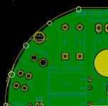
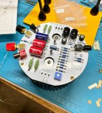
1. I couldn't figure out how to make my PCB CAD package do a circular "zone fill". So instead I inscribed a 20-sided polygon, within the circular boundary of the board, and told the software to pour copper (connected to node GND) in that polygon. A picture of the top left quadrant is shown above; the vertices of the polygon are circled in white. This is kind of a filthy bodge but it actually worked.
2. Some of the components were slightly unusual, and were sourced from unusual vendors. The ones that come to mind at the moment, are shown below.
_
Attachments
Love to read that N. Brock version may make it to the store! VERY COOL. Big thanks to N. Brock and MJ—And Nelson for inspiring it all.
.... We were Friend_B (or A) benefiting from Mark's massive generosity...
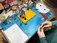
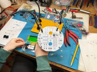
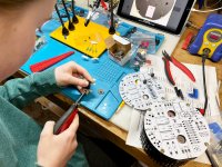
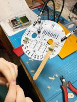
Here's my 11-yr-old daughter starting and almost finishing (Lunch then playdate) one channel (Still have to solder LEDs and mosfets). I had zero involvement in this other than critique on soldering skills and lead bending and general process to build good habits. It's not her first project but it's been a while....
Hopefully some listening later—Will report back with more. The "plan" was that I would build one of them and she the other... apparently that has changed, as I'm not allowed to build the other channel now! I will take that as good sign. She's very proud of her work.
Might be a week before we can complete the full build... school etc.
Yea!

.... We were Friend_B (or A) benefiting from Mark's massive generosity...
Here's my 11-yr-old daughter starting and almost finishing (Lunch then playdate) one channel (Still have to solder LEDs and mosfets). I had zero involvement in this other than critique on soldering skills and lead bending and general process to build good habits. It's not her first project but it's been a while....
Hopefully some listening later—Will report back with more. The "plan" was that I would build one of them and she the other... apparently that has changed, as I'm not allowed to build the other channel now! I will take that as good sign. She's very proud of her work.
Might be a week before we can complete the full build... school etc.
Yea!
Attachments

- Home
- Amplifiers
- Pass Labs
- ACA Redux