Hi
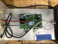
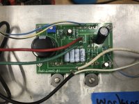
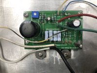
I build my aca's at the first ever amp camp back in 2012. They have served well for over a decade until recently when one of them stoped producing. I checked all the obvious external connections/wires and source and they are all good. I opened it up and that's as far as I've gotten. I don't know what to do next. It is my understanding that is the very first version of the amp. Hoping to repair it so I can pair it back up with the other one and keep on listening.
Thanks for taking interest.
Joe
If you have a volt meter handy start with the power supply. Unplug it from the amp and measure it.
If there is voltage - plug it back in and measure it inside at the supply input connector. Then proceed to the power. Switch and measure it on both sides.
Conversely if there is no voltage. Likely the supply decided to take a vacation.
If there is voltage - plug it back in and measure it inside at the supply input connector. Then proceed to the power. Switch and measure it on both sides.
Conversely if there is no voltage. Likely the supply decided to take a vacation.
The power supply is rated at 19 volts My volt meter may not be the most accurate but it measures 20.1 at the switch (a lighted switch) and 20.1 where the + - attach to the board. The power supply is hardwired (soldiered) to the switch and board so I can not test it separately without braking the soldier joint.
Just noticed you said there was another one. So try swapping supplies with the other one that works.

Hi Dennis,
I have 20.1 volts at the +- on the board.
I know it makes the most sense to trouble shoot this way but question. Given the amp has been working almost daily for the past 10 years I'm wondering if there is component most likely to fail?
I have 20.1 volts at the +- on the board.
I know it makes the most sense to trouble shoot this way but question. Given the amp has been working almost daily for the past 10 years I'm wondering if there is component most likely to fail?
Are your heatsinks warm?
It doesn’t take much current to light the LED.
But is possible that your switch, or power supply connector can no longer sink the current required to turn on and run the amplifier. Kind of like a car with a loose battery cable. The overhead light comes on when you open the door but the current of the starter is too much for the loose connector.
If the heat sinks are cold. Take an alligator clip, or screwdriver and go across the switch and see if the amp will start.
It is time to measure some Voltages. Measure the Voltage across R9 and R15.
Measure the Voltage at the drain of Q1 relative to ground.
If you adjust the trimmer pot, does the Voltage at the drain of Q1 change?
If you adjust the trimmer pot, does the Voltage across R9 change?
Is the LED on?
Post some well lit and focused pictures of the amplifier showing all wiring and connections and pictures of the board.
My board does not have an R 15
I'm not sure which is the drain at Q1
On my working amp at Q1 I get 0 volts (left), 10.5 volt (middle) 4.4 volts (right)
On the non working amp I get 0 volts left 7.6 volts (middle) 7.2 volts right.
One thing to note. the voltage at the middle connection on the non working amp starts around 12 volts and slowly drops to 7.6 volts
What is the Voltage across R9?
If R10 is broken, it needs to be replaced. However if R10 is broken, then adjusting the trimmer should have no effect on the voltage at Q1.
If R10 is broken, it needs to be replaced. However if R10 is broken, then adjusting the trimmer should have no effect on the voltage at Q1.
Again what is the Voltage across R9, and when you adjust the trimmer can you get the Voltage across R9 to approximately 4.5V?
What is the Voltage across R9 of the good channel?
What is the Voltage across R9 of the good channel?
The wire is not broken. If I set the multi meter at 2000k it reads around 275. This amp was working for the past 10 years and just stopped. It is built into a cabinet that does not move. So it should be safe from physical damage. I think something must have burned out.
The voltage across R9
7.1 bad channel
4.4 good channel
yes I can adjust to 4.5 on the bad channel
7.1 bad channel
4.4 good channel
yes I can adjust to 4.5 on the bad channel
You can't measure the resistance of R10 when measuring across the resistor while it's in the circuit.The wire is not broken. If I set the multi meter at 2000k it reads around 275. This amp was working for the past 10 years and just stopped. It is built into a cabinet that does not move. So it should be safe from physical damage. I think something must have burned out.
- Home
- Amplifiers
- Pass Labs
- ACA failed after a decade Help diagnois