Folks - I have gathered components for a stereo single chassis ACA premium build based on the DIYAudio Store kit informed further by this thread. Q1s will be FQH44N10 from a supplier in England, Q2 Crees from Mouser. C1 Mundorf and the balance of the suggested premium bits from Mouser. Rhthatcher kindly provisioned his gorgeous PS filter board and the Digikey BOM for it. Parts will all land this month, and the main kit tomorrow so I can proceed stuffing the PCBs. First pass will be use of the stock brick. The reason I write:
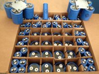
Stage two will be a linear outboard PS. I just sourced a rather massive power transformer, made in Switzerland by Wagner + Grimm AG. Photo and specs att'd. Need your input on the PS schematic / preferred parts / design for simple straightforward great sound. I want to do it point to point, prefer not to use the universal PS and not inclined to regulate, just great filtering and minimal ripple. Transformer is a beast, 12.5lbs. It's coming from England and in the test photos @230V in yields 26V at the secondaries. Thanks in advance, Jim


Stage two will be a linear outboard PS. I just sourced a rather massive power transformer, made in Switzerland by Wagner + Grimm AG. Photo and specs att'd. Need your input on the PS schematic / preferred parts / design for simple straightforward great sound. I want to do it point to point, prefer not to use the universal PS and not inclined to regulate, just great filtering and minimal ripple. Transformer is a beast, 12.5lbs. It's coming from England and in the test photos @230V in yields 26V at the secondaries. Thanks in advance, Jim

Without the inclination to use voltage regulation, a CRCRC filter after the rectifier is recommended. That interesting transformer can be used in a dual-mono supply by virtue of its two secondary windings. So, each channel will have its own bridge rectifier followed by the CRCRC filter.
There are more than a few examples of these if you look around. The ACAs that I built into the old Hafler chassis have 36,000 uF -> 0.5Ω -> 15,000 uF -> 0.11Ω -> 15,000 uF. Find a low Vf block rectifier. It will be more fun that way.
There are more than a few examples of these if you look around. The ACAs that I built into the old Hafler chassis have 36,000 uF -> 0.5Ω -> 15,000 uF -> 0.11Ω -> 15,000 uF. Find a low Vf block rectifier. It will be more fun that way.
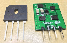
I'm holding out for one of these active rectifiers, if they can get the shipping below $45...
https://evotronix.eu/main/
https://evotronix.eu/main/
Hi AndersonixI'm holding out for one of these active rectifiers, if they can get the shipping below $45...
As i understand the price is 45euro and shipping is 22euro. So are you getting one?🙂
Price: 45 euro, ex VAT
Discount for orders higher than 10 units.
Shipping within EU is 22euro and 38euro outside EU.
Finally got the ACA up and running in bridge mode - at 12.4V bias as suggested I am getting about 52-53 Deg. C on the hestsinks. So far so good but the Meanwell PS brick is getting really warm, is that a concern?
Thank You TungstenAudio, good insights. Can you please recommend a low Vf block rectifier, I like fun!Without the inclination to use voltage regulation, a CRCRC filter after the rectifier is recommended. That interesting transformer can be used in a dual-mono supply by virtue of its two secondary windings. So, each channel will have its own bridge rectifier followed by the CRCRC filter.
There are more than a few examples of these if you look around. The ACAs that I built into the old Hafler chassis have 36,000 uF -> 0.5Ω -> 15,000 uF -> 0.11Ω -> 15,000 uF. Find a low Vf block rectifier. It will be more fun that way.
PCBs now stuffed, soldered and cleaned w/ isopropyl awaiting next step: MOSFET mounting. Recommendations from this thread have been followed for the component build.
I live here too and as you can see am building, I can be a customer or group buy partner 🙂I'm in SF Bay Area, so maybe I should pick up the USA distribution? Here Amazon would drop one off on a Sunday for $19.
That’s a good looking board.
For low Vf block rectifiers, look for the VS-MB series from Vishay.
For low Vf block rectifiers, look for the VS-MB series from Vishay.
Thank you TA. VS-MB's ordered. Meanwhile, chassis assembled and wired first ACA stereo premium build rev1.0, cleaned the wiring points early this morning then powered the amp for an hour. Both sinks exhibiting equal heat dissipation, set voltages at 12.05 volts both channels. Pleased to report it is playing music no issues, dead silent. Rear power switch, with Randy Thatcher low pass filter employed with modifications from this thread, with the exception of 200R R16 forthcoming with linear PS, Swiss transformer lands 27 March by then I'll have the power resistors and caps.
First chip amp for me, these things generate some heat which is nice at the moment in a 56F degree audio shack.

First chip amp for me, these things generate some heat which is nice at the moment in a 56F degree audio shack.
Another path to ACA amp improvement but need some help…First, I want to thank Nelson Pass and the wider DIY community for their creativity and support of audiophiles in search of cost effective solutions.
This is such a great thread. I built a 1.6 kit from the DIYaudio store and although I liked the result, I always wondered what could be…..and then I came upon the aca amp with premium parts thread. This lead me down two paths: 1) to increase the audio quality of the aca with premium parts and 2) obtaining another aca amp so that I could run them in parallel monoblock mode (vs. bridged mono because my speakers are 4 ohm 94db sensitive). I implemented all TungstenAudio’s mods except changing the caps, where instead I soldered 1 microfarad polypropylene caps in parallel with the original kit caps. The results far exceeded my expectations, really good tone. I proceeded to modify the second amp and one channel was good- played and biased as expected, but the other channel would not bias- stuck at 4.65v dc or so regardless of pot adjustment. So I backed out all my mods back to original, but it still won’t bias. Any ideas? Thanks for your help.
This is such a great thread. I built a 1.6 kit from the DIYaudio store and although I liked the result, I always wondered what could be…..and then I came upon the aca amp with premium parts thread. This lead me down two paths: 1) to increase the audio quality of the aca with premium parts and 2) obtaining another aca amp so that I could run them in parallel monoblock mode (vs. bridged mono because my speakers are 4 ohm 94db sensitive). I implemented all TungstenAudio’s mods except changing the caps, where instead I soldered 1 microfarad polypropylene caps in parallel with the original kit caps. The results far exceeded my expectations, really good tone. I proceeded to modify the second amp and one channel was good- played and biased as expected, but the other channel would not bias- stuck at 4.65v dc or so regardless of pot adjustment. So I backed out all my mods back to original, but it still won’t bias. Any ideas? Thanks for your help.
The good news is that you have a working board to use as a reference.
Look closely at Q3 and Q4 to make sure they are installed correctly. Check the values of the resistors, etc..
Look closely at Q3 and Q4 to make sure they are installed correctly. Check the values of the resistors, etc..
Thanks Tungsten. All seems OK and checked out. One item I forgot to mention is that I had the unit running and biasing fine in stock form before implementing your mods sans the different caps. Then had the biasing issue in the right channel so backed everything out (resistors and unsoldered the parallel pp caps) to stock and still can only get 4.6 or so volts on the right channel.
Hi guys,
its long time ago i did some mods on my ACA´s. thanks to nelson and TA!
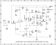
Here is the schematic witch i found years ago for 48V.
please think about your impedance of your speakers because 4R need more current and not more Voltage. so my LS is a 4R and if i modded i bias it to 2Amps. 24V after filter = amp board.
watch your cooling of the MOSFETS !!!
As you can read (please do that) that TA mean that the CCS MOSFET = Q2 should be the MOSFET with the bigger Transcundactance because its helps to "eat" more Ripple from the supply.
Q1 is the sound chip.
IRF044N is not bad😛
go and try out 😉
its long time ago i did some mods on my ACA´s. thanks to nelson and TA!
Here is the schematic witch i found years ago for 48V.
please think about your impedance of your speakers because 4R need more current and not more Voltage. so my LS is a 4R and if i modded i bias it to 2Amps. 24V after filter = amp board.
watch your cooling of the MOSFETS !!!
As you can read (please do that) that TA mean that the CCS MOSFET = Q2 should be the MOSFET with the bigger Transcundactance because its helps to "eat" more Ripple from the supply.
Q1 is the sound chip.
IRF044N is not bad😛
go and try out 😉
Attachments
Last edited:
Added second 24v smps brick. Fabbed a black walnut mount for the power socket in place of the deleted XLR jack. Added second Randy Thatcher low pass filter (these boards were intended for a single brick ps stereo ACA, so I am using have of each of two per channel). The rear panel switch powers one channel, the front panel switch powers the other channel.

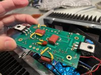
It is always fun to see how the ACA inspires builders to innovate.

A picture of the tricky routing of the 1 microfarad polypropylene caps in parallel with the original DIY kit caps. The results far exceeded my expectations, but still working on one channel of the two amps that I can’t get to bias correctly.
Attachments
- Home
- Amplifiers
- Pass Labs
- ACA amp with premium parts