I am planning an amplification chain consisting of my preamp (Pass B1 with a Korg Triode) followed by the ACA (1.8, stereo, Tungsten version and 2 Meanwell 24V). My electrostatic speakers are nominal 4 ohm and have a sensitivty of 89dB. The only missing Tungsten modification is changing C1 from NP's recommended 3300uF to 4700uF. Would this final modification be asking the ACA to work too hard or has anyone gotten away with it? My music preference is tremble and midrange (mostly classical/vocal) not bass (no heavy metal).
Thanks Robert. The "that guy" section cleared my thoughts and helped me decide to go for 3300uF (first).
Good information regarding coupling caps -
https://www.syclotron.com/why-are-people-obsessed-with-coupling-caps/
https://www.syclotron.com/why-are-people-obsessed-with-coupling-caps/
This (and syclotron's follow-ups) makes me questioning just about every "big" capacitor there are... (like, C3 in a BA3 pre) ...Good information regarding coupling caps -
https://www.syclotron.com/why-are-people-obsessed-with-coupling-caps/
good news are bad news are ... no news 😀
1.
If a dude says: Yea, these caps sounds better than those!
Ask yourself: In what system and do the dude only hear what he wants to hear?
2.
If a dude says: No, these caps sounds exactly like those caps!
Ask yourself: In what system and do the dude only hear what he wants to hear?
3.
A dude measures the caps on the finest existing measuring equipment: and concludes- there are no measurable difference!
Ask your self: Do these ”glorifyed voltmeters” the dude uses really measure and display the right things?
🎷🙂🎸


Parts have finally arrived for this upgrade! As I mark stuff off of my list I have a question regarding R16 and C101.
I have R16 as 1/4W 200 ohm and C101 as 100uf 50V. For now I'll be using the standard 24V power supply. I'm seeing that the real benefit of using these two parts in particular is only for higher power supplies.
Are there any benefits at all if using the standard power supply?
I have R16 as 1/4W 200 ohm and C101 as 100uf 50V. For now I'll be using the standard 24V power supply. I'm seeing that the real benefit of using these two parts in particular is only for higher power supplies.
Are there any benefits at all if using the standard power supply?
Yes, there is still a benefit from these parts with the original 24V supply. That is how I built my first pair of ACAs.
Nice. Thanks! And then my ACAs would be ready should I decide to upgrade the PS...
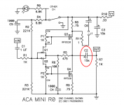
This trace cut, I've read about it but am still not clear. Would it be at either of the two red boxes below? I think the lower one would be easier to work with considering the actual size of the parts. If it's somewhere else, let me know. Thank you!

This trace cut, I've read about it but am still not clear. Would it be at either of the two red boxes below? I think the lower one would be easier to work with considering the actual size of the parts. If it's somewhere else, let me know. Thank you!
Someone had better second this?
yellow line is a break in the track
R between red boxes
see attach image
yellow line is a break in the track
R between red boxes
see attach image
See #112 and #113 with the schematic... describes nicely what he's trying to accomplish....Nice. Thanks! And then my ACAs would be ready should I decide to upgrade the PS...
This trace cut, I've read about it but am still not clear. Would it be at either of the two red boxes below? I think the lower one would be easier to work with considering the actual size of the parts. If it's somewhere else, let me know. Thank you!
No... that's not where I'd cut.
Post @1212 doesn't have an attachment, so I'm not sure if their advice is correct or not.
Mainly... If I were to cut, I'd cut cut between the rail and C4...
Last edited:
Neither of the red boxes are correct.
The new component R16 must be added between V+ and the positive lead of C4. The trace cut should be made close to the V+ wire mount. R16 effectively bridges the cut.
As a clarification, the new C101 is a small 10 pF cap added in parallel with R12.
The new component R16 must be added between V+ and the positive lead of C4. The trace cut should be made close to the V+ wire mount. R16 effectively bridges the cut.
As a clarification, the new C101 is a small 10 pF cap added in parallel with R12.
Okay, I am definitely getting these mixed up.
For the record, as near as I can tell:
R12: the values changes from 39.2k to 90.9k and gains a parallel C101 which is a 10pf silver mica cap.
R16 is new and is added between V+ and the positive lead of C4.
Other notes in this thread mention that R16 can benefit from a parallel 100uf 50V cap.
Finally, I believe R16 will have an effect on the drain of Q4 since there is now resistance on that line.
This makes sense to me now after reading post #928 where Tungsten said, "...I would probably cut the trace rather than trying to lift one leg of Q4."
So the cut goes somewhere along the new red box area and R16 bridges the connection. (Picture...thousand words...etc.)
If not, the comedy show will continue!
Thanks to all of you for your help. The answers and references really made a difference.
This one looks good.
Check the other side of the board and see how V+ is routed to the other components where it is needed. Just for your understanding.
When cutting the trace on the top side, be careful not to use too much force. Inspect your work with a magnifier to confirm that the connection has been severed.
Check the other side of the board and see how V+ is routed to the other components where it is needed. Just for your understanding.
When cutting the trace on the top side, be careful not to use too much force. Inspect your work with a magnifier to confirm that the connection has been severed.
Last edited:
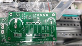
That is a different PCB, likely sourced from China. With no acknowledgement of Nelson as the designer.
You are on your own with that one.
You are on your own with that one.
- Home
- Amplifiers
- Pass Labs
- ACA amp with premium parts