Yes, metalized mylar will burst into flame from a stator to metalized mylar arc.Is this a true danger using metallized mylar as a diaphragm ? I am building a wire segmented stator using pvc insulated copper wire and have purchased some emergency blankets (12 micron aluminized mylar) for diaphragm usage.
I have tested this several times (using emergency blanket material actually) with the same result.
However, if you are using PVC insulated wire stators, you should not have any problems since you won't be able to form an arc. If you exceed the air breakdown voltage, the bulk resistivity of the PVC will limit the current so that you will only get corona discharge rather than an arc. With lights off it looks something like this: Stator Corona discharge
Of course ozone is generated during the corona discharge which isn't good for your health either, but it is better than flames.
It depends on the distance the ribs have to span and what material is used.i.e. how "tall" should the ribs of the frame be? (rule of thumb, if any).
I would recommend trying out a couple different rib heights spanning the spacer distance you plan to use in your stators and push on it in the middle of the span...with your thumb if you like 😉 The rule of thumb is that you would like minimal deflection with a few lbs of force applied and enough area to provide a good glue joint with the PVC wire. Depending on the material used, you may also need to consider how it might warp over time with changing temperature or humdity.
Some additional examples to add to CharlieM's...
For spanning 3.25" I have used 1/2" tall x 1/8" wide phenolic ribs.
For spanning 7", I have used 1/4" x 1/4" T6061 aluminum.
I was just thinking of spanning the whole width (14" ish), with 3/4" high ribs, without vertical supports. Good idea or bad idea? Thinking of using plastic or wood. Little leary about using metal due to its conductivity.
This wire is .052" O.D. which spaces to 43% open if you use 12TPI threaded rods to space the wires.
Just doing a little sanity check here.... I found a table someone posted on some thread about this that .052 O.D. wire would be 32.4% open if 13 TPI and 42.8% open if 11 TPI. Based on that, I would expect 12 TPI to be <42.8%.
I was thinking of going with 11 TPI (since I can use the bigger 5/8 rod for my stretching jig 🙂 ); which the table I have says 42.8%.
Just want make sure I have the math right (not my strong suit either 🙂 ).
I'm not sure what TPI CharlieM used, but I think the table you were talking about was this one:
http://www.diyaudio.com/forums/planars-exotics/281348-sanity-check-wire-stator.html#post4492349
For wire stators you can calculate the % open area by multiplying the OD times the number of wires per inch, and then subtracting it from 1.
For your example:
OD=0.052, 11 wires per inch
%open area = (1 - 0.052 x 11) = 0.428 = 42.8%
Will work great
Cool, thanks for the sanity check (and yes, that was the very table I was talking about).
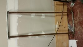
Just spent the past few hours building my jig, got it mostly done - have a couple things left to do but it is pretty much done. It is made from 1" steel square tubing welded together, so it will be *plenty* strong.
Once I get it all together I will post some pictures in the next day or so.
Thanks again for all the help from everyone.
I'm not sure what TPI CharlieM used, but I think the table you were talking about was this one:
http://www.diyaudio.com/forums/planars-exotics/281348-sanity-check-wire-stator.html#post4492349
For wire stators you can calculate the % open area by multiplying the OD times the number of wires per inch, and then subtracting it from 1.
For your example:
OD=0.052, 11 wires per inch
%open area = (1 - 0.052 x 11) = 0.428 = 42.8%
Will work great
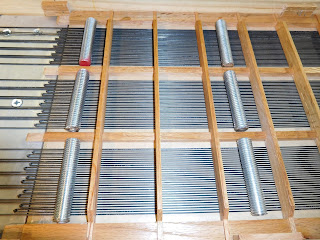
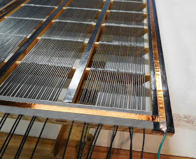
11 TPI is correct. If I said 12TPI in an earlier post, then I was mistaken. See the photo below: Even though I used 1/16" pins to hook and pull the wires, I used 11TPI x 5/8 all-thread rods to properly space them with about 43% open area.
Just curious, did your wires shrink after stretching? I.e. smaller diameter
I didnt measure their diamater before & after stretching so I cant say. However, I only stretched them 1% so I would assume a similar 1% reduction in diameter.
Have a safety question....
Given that I have a 3 year old and have other children around while the speakers are playing and given that I will be using PVC insulated wire stators...... should I put speaker grills on? i.e. is the PVC insulation enough and reliable protection against serious shocks etc....?
Given that I have a 3 year old and have other children around while the speakers are playing and given that I will be using PVC insulated wire stators...... should I put speaker grills on? i.e. is the PVC insulation enough and reliable protection against serious shocks etc....?
PVC insulation is perfectly safe as far as electrical shock is concerned.
You can touch front and rear stators at the same time without worry.
However, with children around it may still be a good idea to think of some form of protection...for the PVC wires not the children 😉
Unlike steel rods, they can be pushed on hard enough to permanently deform.
This is the ESL equivalent of kids thinking dome tweeters are buttons that need to be pushed.
Kids and cats!
For sure, you want 30 megOhms to be between your bias circuit and the output of the box that holds your bias supply.
Anybody have the authentic numbers for the resistance?
B.
For sure, you want 30 megOhms to be between your bias circuit and the output of the box that holds your bias supply.
Anybody have the authentic numbers for the resistance?
B.
However, with children around it may still be a good idea to think of some form of protection...for the PVC wires not the children 😉
Unlike steel rods, they can be pushed on hard enough to permanently deform.
This is the ESL equivalent of kids thinking dome tweeters are buttons that need to be pushed.
Yeah, that is a good point I hadn't thought of. With the more open grid it would be too easy to get little hands in there.
So building so prototype supporting grids as we speak....and had a couple of questions.
My intent is to make them out of 1/2" veneered plywood (though I plan to paint them, I've just found over the years veneered ply tends to have few voids).
I plan to do 2 vertical bars equidistant over the width and the dimensions being 1/2" thick (height) X 3/8" (maybe 1/4") wide. The horizon supports will run every 3" or so down the vertical. The supports would be 1/2" x 1/2"
All the grids will be dado'ed and glued together. "Ends" of the grid will be dado'ed (rabbited technically) and glued into the surrounding frame.
Sound reasonable?
Also, curious about what do with the wires that are "covered" by the vertical supports. From looking at charile's build, looks like I would just "skip" over them, i.e. not count those wires as part of the segment(s) they are in? Kind of concerned about a vertical "gap" in the segments.
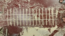
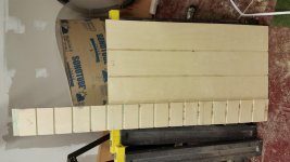
Attached are some pictures of my prototype (and maybe real) grid.
It isn't too difficult to "mass produce" these once you get the initial dado cuts setup (and the requisite tweaking with the stacked cutter for my tablesaw).
Once the slots are cut then you can rip/crosscut all the pieces needed to assemble many grids.
The grid is 1/2" X 14" wide (H), 3/8" wide X 48" h (V). I figured it I wanted a smallest width I could get away with on the vertical supports and go a little wider on the horizontal. I am not exactly thrilled with giving away 20% of the panel area to the grid - but what are you going to do? 🙂
Also attached is a picture of my stretching jig, which isn't completely done yet. I will post some more to show it "in action".
Attachments
Last edited:
I plan to do 2 vertical bars equidistant over the width and the dimensions being 1/2" thick (height) X 3/8" (maybe 1/4") wide.
Also, curious about what do with the wires that are "covered" by the vertical supports. From looking at charile's build, looks like I would just "skip" over them, i.e. not count those wires as part of the segment(s) they are in? Kind of concerned about a vertical "gap" in the segments.
Have a look at the photo below. In my build, the vertical slats not only support the horizontal slats, they are also pads for the two center diaphragm support spacers (I opted for vertical rather than horizontal diaphragm supports) There was no point in placing wires where they can't drive the diaphragm-- this would only add capacitance that doesn't contribute to output.
Since I opted for vertical diaphragm supports, the horizontal wire supports didn't need to be larger than 3/16"-- to minimize the closed area over the wires. With E6000 glue, a 3/16" wide glue line is sufficient to hold the wires.
Last edited:
How "high" are your horizontal supports? Given my stretching jig, I am limited in how high I can make them. I probably could get away with 3/8" on the width of the horizontal supports but not sure I should press my luck 🙂. The most important dimension for stiffness is the "height" of the supports (section modulus) and I can't go much "higher" in thickness.
With the wires on the vertical supports, I was planning to not hook them up they would just be in there dead.
I am curious if I should make adjustments to bolserst's spreadsheet to the effective panel width (and height)... thinking about the accuracy of the resistor values for the segments.
With the wires on the vertical supports, I was planning to not hook them up they would just be in there dead.
I am curious if I should make adjustments to bolserst's spreadsheet to the effective panel width (and height)... thinking about the accuracy of the resistor values for the segments.
For the sake of our discussion "height" shall mean height above the wires, "width" the span across the panel and "thickness" meaning vertical width.
My horizontal supports are 11/16" height x 3/16 thickness x 12" wide.
If you opt for vertical diaphragm supports, they should be at least 3/8" wide. If you opt for horizontal diaphragm supports, then vertical supports can be as thin as you like to minimize their obstruction. If your diaphragm support spacers are run horizontal the diaphragm can still be driven under the vertical slats and partially contribute to output; in which case you might as well continue the wires under the vertical slats.
It doesn't matter whether your diaphragm supports are vertical or horizontal-- it will sound fabulous either way. And if you're supports are a bit thicker than needed, you will lose a small portion of output but it will still sound fabulous.
The length & width inputs into the spread sheet should reflect the wire area exactly (not panel area unless they are the same).
Last edited:
Thanks... those are pretty "high" @ 11/16"... I hope my 8/16" will do the job 🙂.
I reworked the grid tonight and decided to go with 3/8" wide the for both vertical and horizontal and increased the spacing a bit to 2 7/8".... it seems plenty stiff enough to me so I hope I don't come to regret it.
The vertical supports are about 4 5/8" wide spaced across the diaphragm this keeps me on the low end of the "70 - 100" X d/s rule since I plan to do vertical spacers.
That means I have 14 horizontal supports and 2 vertical ones. This shaved off about 5% or so off the diaphragm area loss.
I was planning to go ahead and just "wire" the vertical spacers anyways since I think it would be too much hassle to work around it with the kind of stretching jig I have. I think my panels will have to come in at about 14.5" wide so I can "skip over" (not connect) the vertical support wires and have an "even" number of wires in the physical segments.
I'm sure they will sound awesome. I just tend to fret over alot over the little theoretical stuff.... e.g. I briefly entertained rounding over the grid supports to minimize diffraction effects (came to my senses when I realized it mostly a problem at low frequencies).
I am somewhat concerned (maybe curious is a better word) about what happens to the polar dispersion with 2X 3/8" "gaps" in the wavefront.
BTW thanks for all the help, I was thinking the other day I've progressed from wanting to build perf panel - to - TIG wire - to - stretched wire stators in a few months thanks to the folks on this forum pioneering DIY efforts...... it appears to have saved me years of learning/effort 🙂.
yikes....the vertical spacers are adding some complexity that I didn't intend on... (or I am over thinking it 🙂 ).
Ideally, I would think I would want the physical segments to "end" right at the vertical spacer so you can "jump over" it and start the next physical segment. Otherwise you would have to split up the physical segment to jump over the vertical spacer. i.e. say you have 6 wires in a physical segment (12 electrical) and you are 4 wires into a segment when you meet the vertical spacer. You then would have to skip over 3/8" (in my case) and continue with 2 more wires.
Is this even a big deal?
I am not entirely sure what to put into the spreadsheet at this point. I was thinking I would just make the panel 14.81 (13/16") inches wide (163 wires @ 11 TPI) and subtracting out the 2 3/8" wide spacers leaves me at about 14" wire width.
The complication, for me anyways, that given I will have 11 wires per inch, is trying to calculate out physical segments that will come out with non fractional wires 🙂.
Like to make an enhancement request to bolserst's spreadsheet 🙂.... such that you could say - I would like my panels somewhere around X inches wide.... and I plan to have X wires per inch.... so what would be the ideal width of the panel be to have non fractional wires per physical segment (given the segment # you input).....
I would appreciate any help with the math here, I feel like I am missing something simple.
BTW I do have some "wiggle room" in the width of my panels. I made the grids 16" wide since I am going to dado them into the frame rails, so I can go anywhere between 13" to 15" in width.
Also, currently my vertical spacers are 5.25" from the edges with 4.625" between the center (basically subtracting out the 2X 3/8" wide spacer).
- Home
- Loudspeakers
- Planars & Exotics
- About to take the ESL plunge