Pretty crazy how much force can build up from stretching multiple thin wires. 😱
Glad to hear you have a game plan to salvage what you can from the wires already wound on the jig.
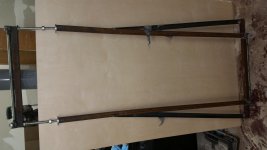
I use solid 2" T6061 aluminum bars for the ends of my stretcher and they still bow in about 1/16" in the middle of the span when stretching.
Glad to hear you have a game plan to salvage what you can from the wires already wound on the jig.
I use solid 2" T6061 aluminum bars for the ends of my stretcher and they still bow in about 1/16" in the middle of the span when stretching.
I am always amazed how much leverage a bolt and nut have. I can gingerly turn a nut with a hand wrench to generate that much force.
How will the final structure keep the integrity then? I am afraid that being so flat it will end up with propeller like shape. As copper wires are stretched above yield point and will not act as a spring would not it be reasonable to release tension before gluing?
I would agree with Alexberg on this. Beyond the yield point wire tension will remain constant with an increased stretch (neglecting the strain hardening etc).The purpose of this should be to align and straighten wires. If the tension is left, then panels may/will warp due to uneven relaxation of wires. It will also increase the panel natural frequency (not the membrane resonance freq). The only way to fix this is to have very, very rigid frame and continuous clamping of panels around their perimeter.
Regards
Regards
I have had a pr of Audiostat 100 that have great output an sound...even if there is a 30mf cap..... on the pos input to the primary of the sepup tran......an each of the panels wires can be move 1/4"....this tell me that there not as much stretching ....as your trying to get here...
So.....Why so much wire stress here??
thanks for any input.....
So.....Why so much wire stress here??
thanks for any input.....
As mentioned in other solid PVC wire stator build threads, the wire is stretched 2% - 6% to straighten and cold work(strengthen) the copper wire. Then, tension is released and the wires glued to the frame. The completed stator frames lay perfectly flat with no warping.... Beyond the yield point wire tension will remain constant with an increased stretch (neglecting the strain hardening etc).The purpose of this should be to align and straighten wires. If the tension is left, then panels may/will warp due to uneven relaxation of wires...
I stretched my wires somewhere around 1%-2%. Enough to get them very straight and flat. I released most of the tension but left a little to keep the wires straight and then glued them down.
I am concerned as well about the residual tension being left in the grid frame that may cause it to warp. I won't know until I release all of the tension on it remove it from the jig.
Also noteworthy is I am using the E6000 glue which does "give" a little bit when dry so that might help as well.
I am concerned as well about the residual tension being left in the grid frame that may cause it to warp. I won't know until I release all of the tension on it remove it from the jig.
Also noteworthy is I am using the E6000 glue which does "give" a little bit when dry so that might help as well.
Last edited:
I just realized that with the method you are using, residual tension should be much less of a problem. You will be cutting the ends of the wires at top and bottom. Since you stretched the copper wire and it's diameter decreased slightly, it should relieve all tension by shortening inside the PVC insulation tube that is glued to your frame. The only tension your frame should need to resist would be that of the stretched PVC insulation which is not much.... I released most of the tension but left a little to keep the wires straight and then glued them down...I won't know until I release all of the tension on it remove it from the jig.
With the method CharlieM and I use where the ends of the wires are not terminated but wrapped back and forth around pins, it is much more important to release as much tension as possible before gluing down the wires.
I just realized that with the method you are using, residual tension should be much less of a problem. You will be cutting the ends of the wires at top and bottom. Since you stretched the copper wire and it's diameter decreased slightly, it should relieve all tension by shortening inside the PVC insulation tube that is glued to your frame. The only tension your frame should need to resist would be that of the stretched PVC insulation which is not much.
Hmmmm, that is very interesting, never even thought of that.
Just for fun, I did measure a stretched piece of wire diameter that I removed from the jig against the unstretched and didn't measure much difference.
Presuming it scales lineally, I stretched the wire about 1% ish... that would result in a .0005-ish reduction in diameter (if I math'd it right).... which is well beyond the accuracy of my calipers 🙂.
I would guess it is a function of how well the PVC sticks to the copper wire... given how easily it is stripped, I would guess not much.
I have a prototype throw away grid; so if I have some wire left over I will stretch to 2% or so and glue it down to the frame at full tension and see what happens.
Bolserts is correct, the tension would be kept in the frame only if you solder the wires before cutting them. PVC will quickly lose (any) tension due to relaxation.
Regards
Regards
Been out of town etc... for a awhile since I last posted so I thought I would give an update.
I've completed one set of wire stator panels (2 more to go). Had a lot of difficulty dealing with only being able to partially wind a pair due to the jig bending but managed to get together a set of grids that are a "matched" pair. Aesthetically, I am not terribly happy as the space on the vertical spacer is not symmetrical but I do have 3 groups of 49 wires (7 per physical seg).
So, one lesson learned here is do not underestimate the strength need for the tensioning jig, especially for wider panels. I saw a picture one jig made out of wood and I don't know how that worked unless they were fairly narrow panels (didn't have a good sense of scale).
I am not entirely happy with the E6000 glue either. I used the medium visocity, self leveling glue variety and I found myself "pushing" the glue down thru the wires (in my case it is applied on top of the wires and soaks thru to the grid frame). It did "level" pretty good but it is not flush with the wires... you can feel a little bump with your hands as you go over it. With the spacing running about .065 I worry about every .01 inch 🙂.
Next steps is to wind up the next set, which I expect to go significantly smoother with the mark 2 version of my stretcher...... though... believe it or not; it is still not strong enough for my liking.... but it is good enough to get the job done.
After that it is onto putting the grids in the frames. Got the wood ripped down to 1.5" wide and ready to start making those. I decided to make them out of walnut and the box part out of veneered walnut. I love walnut and always wimped out at using walnut in past speaker builds due to the cost... but I finally got the courage (and cash) to bite the bullet and do these speakers in walnut this time around.
The plan is to build the frames and cut 3/8" (width of grid rails) slots into the sides/top of the frame to recess the frames down into it. I still have an open question on whether I am going to recess the wires flush with the back of the frame or leave the wires sitting "on top" of the top/bottom rail (and thus be sitting not flush with the side rails).
I am still debating on how I am going to deal with the spacers and edge tape thickness problems to get it to all work out right. Love some advice here.
e.g. one scenario I have in mind I would have to double stack .065 tape on the side rails that would give me a .078 d/s spacing.... might be a little pessimistic but with all the wood(and its ever changing state with warp,twist etc...), glue not flat etc... etc... thinking have a little extra d/s might not be a bad idea even if it costs me efficiency.
Good idea to double stack foam tape? i.e is it stable enough?
I've attached some pictures.
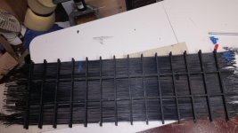
Attachments
Last edited:
Been out of town etc... for a awhile since I last posted so I thought I would give an update.
I've completed one set of wire stator panels (2 more to go). Had a lot of difficulty dealing with only being able to partially wind a pair due to the jig bending but managed to get together a set of grids that are a "matched" pair. Aesthetically, I am not terribly happy as the space on the vertical spacer is not symmetrical but I do have 3 groups of 49 wires (7 per physical seg).
So, one lesson learned here is do not underestimate the strength need for the tensioning jig, especially for wider panels. I saw a picture one jig made out of wood and I don't know how that worked unless they were fairly narrow panels (didn't have a good sense of scale).
I am not entirely happy with the E6000 glue either. I used the medium visocity, self leveling glue variety and I found myself "pushing" the glue down thru the wires (in my case it is applied on top of the wires and soaks thru to the grid frame). It did "level" pretty good but it is not flush with the wires... you can feel a little bump with your hands as you go over it. With the spacing running about .065 I worry about every .01 inch 🙂.
Next steps is to wind up the next set, which I expect to go significantly smoother with the mark 2 version of my stretcher...... though... believe it or not; it is still not strong enough for my liking.... but it is good enough to get the job done.
After that it is onto putting the grids in the frames. Got the wood ripped down to 1.5" wide and ready to start making those. I decided to make them out of walnut and the box part out of veneered walnut. I love walnut and always wimped out at using walnut in past speaker builds due to the cost... but I finally got the courage (and cash) to bite the bullet and do these speakers in walnut this time around.
The plan is to build the frames and cut 3/8" (width of grid rails) slots into the sides/top of the frame to recess the frames down into it. I still have an open question on whether I am going to recess the wires flush with the back of the frame or leave the wires sitting "on top" of the top/bottom rail (and thus be sitting not flush with the side rails).
I am still debating on how I am going to deal with the spacers and edge tape thickness problems to get it to all work out right. Love some advice here.
e.g. one scenario I have in mind I would have to double stack .065 tape on the side rails that would give me a .078 d/s spacing.... might be a little pessimistic but with all the wood(and its ever changing state with warp,twist etc...), glue not flat etc... etc... thinking have a little extra d/s might not be a bad idea even if it costs me efficiency.
Good idea to double stack foam tape? i.e is it stable enough?
I've attached some pictures.
Glad to see you're back on track (also wondering if you saw the PM I sent you a couple of weeks ago).
I haven't tried double stacking foam tape. It would probably work OK, although there would be at least twice the lateral creep in holding the diaphragm tension.
From the photo of your panel I don't see any edge members along the sides and ends to attach the foam tape spacers to. Just wondering how you're going to do that.
I was going to suggest that you slice up some wooden spacers on a table saw of same thickness as the wires, rather than using two layers of foam tape-- but I don't see any edge members to support the spacers.
Glad to see you're back on track (also wondering if you saw the PM I sent you a couple of weeks ago).
Actually, I have quite a few PM's I haven't noticed or read ... so sorry to the folks who sent them, I just never noticed them 🙂.
I haven't tried double stacking foam tape. It would probably work OK, although there would be at least twice the lateral creep in holding the diaphragm tension.
From the photo of your panel I don't see any edge members along the sides and ends to attach the foam tape spacers to. Just wondering how you're going to do that.
I was going to suggest that you slice up some wooden spacers on a table saw of same thickness as the wires, rather than using two layers of foam tape-- but I don't see any edge members to support the spacers.
The grids are not yet attached to the walnut frames. My plan is to build the frames, then cut little dado's into the frames to put the grid rails into. i.e. the grids are currently separated from the frames. So once in the frame, the frame rails will be the support.
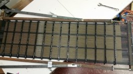
Quick update. Got the next 2 stator wires glued down to the frames. Stretching was much easier with the modified jig (though still had to fight twisting issues).
Next onto the woodworking piece to make the frames and hope and pray that everything lays flat to much less than 1/16" tolerance so the diaphragm doesn't touch the stators in places (not feeling all that optimistic 🙂 ).
Next onto the woodworking piece to make the frames and hope and pray that everything lays flat to much less than 1/16" tolerance so the diaphragm doesn't touch the stators in places (not feeling all that optimistic 🙂 ).
Attachments
Wondering if you guys can help me get past some analysis paralysis here.....
Trying to decide what the bias voltage should be. Sander's book gives a guide line and generally you want it as high as possible but if it is too high you run into stability problems (the diaphragm will bow and maybe touch the stators etc....).
Design goal is I would like have the option of a real SPL level of 100 dB @ 15 feet (though my normal "loud" listening levels are somewhere in the low 90's). The speakers going to be in a large room.
My transformer step up is 129:1 (more to come on that, BTW) so thinking around 3800V.... but would like to go higher... to maximize my SPL potential (in case of construction tolerance problems with spacing etc... etc....).
Theoretical Max SPL predicted from Bolserst's spreadsheet is 101dB with these parameters.
pros/cons with higher bias voltages????
h: 48.00 (in) height
w: 13.36 (in) width
d: 0.0730 (in) gap
r: 15.0000 (ft) distance
A: 0.4137 (m^2) area (panel)
h: 1.2192 (m) height
d: 0.0019 (m) gap
Vpol: 3,708 (VDC) Vbias (optimal)
Vsig: 7,417 (Vpeak) Vsignal (max/optimal)
N: 12 # sections
fL: 250.00 (Hz) LFbreak pt
fH: 144000.00 (Hz) HFbreak pt
R: 53.73 (Kohms) Feed Resistance
Ctot: 987.35 (pF) Cpanel
C: 82.28 (pF) Csection
w(sec): 1.11 (in) width section
39.65 (Vrms) input limit
Vin: 28.00 (Vrms) amplifier voltage
Step-Up: 129.0 step-up ratio
Vbias 3,800.0 (VDC) bias voltage
Line Source: Finite Type of Line Source
Vstators 3,612 (Vrms) stator-to-stator voltage
5,108 (Vpeak) stator-to-stator voltage
Fs: 120.00 (Hz) Resonance Frequency
Q: 10.0 Resonance Q
Last edited:
Trying to decide what the bias voltage should be.
It would be nice to have a general method for all of us for setting max safe bias. In the abstract, you'd want a repeatable non-destructive method. Like "start of sizzle sounds when the input signal loudest desired and you creep up the humidity to 80%".
Wouldn't the use of extremely high resistance coatings on the film prevent catastrophes?
Takes a day for my Dayton-Wright cells (in free air) to get fully biased.
The consistency of output loudness of an ESL matters a lot because it has to work with a subwoofer. So you can't live with changing bias day by day.
Good to have a variable bias supply. Easy with ladders because you can make an alligator clip for the output lead and clip to any step of the ladder you want. I use an EMCO little black brick together with a variable 15VDC supply to drive it* - couldn't be nicer (if you can buy one second-hand).
Flash Bulletin from the Even Old Guys Learn Something New Department: yes, you really do need heavy speaker lead wires (amp to matching transformers) because the transformers can go real low on input impedance at lowest and highest frequencies. Good idea to run impedance tests on the transformers (very easy, first run REW curves to calibrate using a dummy one-Ohm and three-Ohm resistors in place of the transformer; that shows what "curves" you get with one and three and then see where the transformer falls).
Ben
*like $10 on eBay and even has a voltage display.... sadly, I can't see the display since it is inside the strong metal box that holds the matching transformers etc, but I calibrated the knob (of the control pot) that is sticking outside the box. Couldn't be nicer.
Last edited:
Wouldn't the use of extremely high resistance coatings on the film prevent catastrophes?
Takes a day for my Dayton-Wright cells (in free air) to get fully biased.
Yes it would, which I plan to do but I got a little spooked by sanders when he describes the bowing effect where the diaphragm doesn't sit perfectly in the gap. It bows towards one stator or the other....the higher the bias voltage, the stronger the effect until it sticks to the stator (then may oscillate as it discharges the diaphragm and recharges).
Takes a day? How much resistance does the bias circuit have? I was thinking that at 20 MOhm is would take a minute or so to fully charge (never did the math though).
Takes a day? How much resistance does the bias circuit have? I was thinking that at 20 MOhm is would take a minute or so to fully charge (never did the math though).
I don't know about diaphragm resistances. But the series resistors I use are like 50megOhm (give or take 20 Meg), but which may be a small part of the total.
Too bad it isn't feasible to measure resistances, leakage, sparks, and other parameters of interest to ESL builders. As in previous post, good if this forum could discuss measurement/evaluation methods*.
Ben
*My goal in life is to reproduce good looking square waves at ear level. Can't even come close to capturing square waves even an inch from my cells.
BTW, thanks for the tip on the EMCO supplies....
Until now, I always figured I would be building a ladder circuit for the bias but looks like there is a universe of HV supplies out there that might be cheaper than building one.... poking around the forums about this now 🙂.
Until now, I always figured I would be building a ladder circuit for the bias but looks like there is a universe of HV supplies out there that might be cheaper than building one.... poking around the forums about this now 🙂.
BTW, thanks for the tip on the EMCO supplies....
Might run about us$70 on eBay, plus DC supply (variable models run on 0-12 or 15v and quite linear with input voltage). Centre-tap output or not, shouldn't make a difference which one you get.
I've bought three and they all work OK and seem to have internal protections, isolations, etc. that are favourable for our purposes. They will also put out higher voltages than rated (at your own risk, of course).
Wattage rating prolly not important. But...... doesn't take much amperes to exceed a watt or three limit when you are at 8000 Volts. Do the math to see you need a real big series resistor to keep within one watt if a short should occur.*
Far more lethal than a ladder. But a very sanitary minimum parts-count set up.
Ben
*And hopefully, the short isn't YOU
Last edited:
- Home
- Loudspeakers
- Planars & Exotics
- About to take the ESL plunge