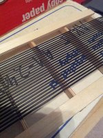
See attached (it isn't to scale) ... These are the grids I currently have built.
The are 16" wide, so I have some extra "room" to get to the width I need. The height isn't exactly relevant to this but it is 50" or so.
The frames are not built yet as I am trying to figure out exactly what width I need for the stators (grid width).
The are 16" wide, so I have some extra "room" to get to the width I need. The height isn't exactly relevant to this but it is 50" or so.
The frames are not built yet as I am trying to figure out exactly what width I need for the stators (grid width).
Attachments
If you plan to section the diaphragm into three vertical segments (as I did), then I would not run wires over the center support spacers, as they would only add capacitance without contributing to output. If you must run wires where the spacers will be for stretching, clip them out after stretching.
Also, there is no point in placing wires over areas of the diaphragm that are not free to move. And the diaphragm is not free to move where it's constrained by the spacers. Accordingly; I would not place wires closer than about 3/16" from the spacers. In my panels the wires are .30" from the spacers.
Assuming you are locked into the 4.625" center span but you can adjust the outer spans, you could adjust your panel size to segment the diaphragm into equal thirds; each with 4.625" open span between support spacers.
This would give you the following option:
Five 9-wire groups would fit nicely into each span with 0.31" clearance to the spacers.
So you would end up with (15) 9-wire groups = 135 wires total. Completely symmetrical.
If you plan to section the diaphragm into three vertical segments (as I did), then I would not run wires over the center support spacers, as they would only add capacitance without contributing to output. If you must run wires where the spacers will be for stretching, clip them out after stretching.
My thought here is it would save me from the tedium of trying to not glue down the wires over the vertical spacers. i.e. I just run the glue straight across. If I leave the wires and simply do not connect them to the step up transformer, I won't have any extra shunt capacitance, right?
It also saves me from having to "make up" the .05 height I lose in the D/S spacing. Though I suppose I could just stack up 2 thicknesses of 1/16 tape and end up with a D/S of .073 instead... though I lose 3db or so in SPL.
This would give you the following option:
Five 9-wire groups would fit nicely into each span with 0.31" clearance to the spacers.
So you would end up with (15) 9-wire groups = 135 wires total. Completely symmetrical.
I kinda get what you are saying about not having wires run right up the spacer since you are adding capacitance for little to no output next to that vertical spacer but trying to understand this in the context of using horizontal spacers.... seems like horizontal spacers would be significantly worse because there are more of them.
So the 5/16" (.31) clearance to the spacers in on each side or is this the total?
So this would give me 8 electrical segments.... A physical stator panel width of 14 5/8" with the actual wire/diaphragm panel width of something like 12 1/4"? Thinking thru what values would get punched into bolserst's spreadsheet to figure out resistor values (etc).
I was hoping for 10ish segments for better dispersion but understand this is the "fractional" wire problem 🙂.
Also, bit concerned about having 2, .675" wide (.30 +3/8") gaps across the front in terms of polar response/dispersion.
Again, thanks for all the help....
My thought here is it would save me from the tedium of trying to not glue down the wires over the vertical spacers. i.e. I just run the glue straight across. If I leave the wires and simply do not connect them to the step up transformer, I won't have any extra shunt capacitance, right?
It also saves me from having to "make up" the .05 height I lose in the D/S spacing. Though I suppose I could just stack up 2 thicknesses of 1/16 tape and end up with a D/S of .073 instead... though I lose 3db or so in SPL.
I kinda get what you are saying about not having wires run right up the spacer since you are adding capacitance for little to no output next to that vertical spacer but trying to understand this in the context of using horizontal spacers.... seems like horizontal spacers would be significantly worse because there are more of them.
So the 5/16" (.31) clearance to the spacers in on each side or is this the total?
So this would give me 8 electrical segments.... A physical stator panel width of 14 5/8" with the actual wire/diaphragm panel width of something like 12 1/4"? Thinking thru what values would get punched into bolserst's spreadsheet to figure out resistor values (etc).
I was hoping for 10ish segments for better dispersion but understand this is the "fractional" wire problem 🙂.
Also, bit concerned about having 2, .675" wide (.30 +3/8") gaps across the front in terms of polar response/dispersion.
Again, thanks for all the help....
I too had concerns about possible effects on the polar response if using vertical spacers. Obviously, the gaps produced by the vertical spacers must have some effect that you wouldn't get if you used horizontal spacers.
What convinced me to go with vertical spacers was JamesThomas' excellent speaker build and the results posted HERE.
BTW, the gaps would be .30 + 3/8" + .30; which would still be rather less than the wavelength a couple of octaves down the ladder where the gaps would occur. (a wavelength @ 5Khz is about 2.6")
BTW, wires do not provide much surface area for foam tape to grab onto, so you might want to reconsider. If you remove the wires over the vertical spacers you could glue down wood strips flush to the wires. You could cut the wood strips on your table saw; although it may take you a few tries to get the fence dialed in. The wires that lap onto the stator frame at the panel ends are a different situation.
On my build I used 1/16” foam tape spacers everywhere except at the panel ends where the wires lap over the stator frame. There I glued down a strip of 3/64” thick polycarbonate over the wires, followed by .015” UHB foam tape (all purchased from McMaster-Carr).
On my build I used 1/16” foam tape spacers everywhere except at the panel ends where the wires lap over the stator frame. There I glued down a strip of 3/64” thick polycarbonate over the wires, followed by .015” UHB foam tape (all purchased from McMaster-Carr).
Lot to think about here... With the vertical spacers I would be losing about 1.25" inches in driven panel width but I guess that isn't too bad.
Just not sure I need to leave so much of a gap around the center spacer; as I would think I would need to do the same at the edge (where the mylar is stuck the frame). Even though it isn't moving the diaphragm much next to the spacer, it has to be helping. I have the picture if the bowed diaphragm from Sander's book in my head.
Sanders also mentioned not to worry about 10% or so stray capacitence..... but maybe worry about it on large panels (not entire sure if mine are consider "large").
I would also like a couple of more segments (10 perhaps).... trying to crunch the numbers to see if I can make that happen.
Still confused on what I should put into the spreadsheet to account for whatever vertical spacer/wire configuration I come up with.
Point taken on the foam spacer/wire surface area..... I thought I could just run a bead of e6000 glue down the vertical and put the foam on top of that. I am not entirely sure I will even "stick" the foam to the mylar on the verticals (leave the backing paper on). Not much reason to; as the grids are anchored into the frames.
I'll experiment a bit when I start winding the wire around the grids. I maybe able to just basically wind 3 separate vertical sections.
1st I need to come up with a wire segment plan and come to peace with it 🙂
The only other option I was able to come up with is 7, 7 wires physical segments for each 4 5/8 section. That only leaves me with about .09 (little better than 1/16") space on each side of the vertical spacer.
In total, this gives me 11 electrical segments for a "wire" panel width of 13.36" and physical panel width of 13.875".
Granted in this config, the 1st 2 wires on either side of the spacers is not going to be doing much to drive the diaphragm, so I am throwing away about 8 "wires worth" of stray capacitance........ I *think* this is about 100 pF of stray but not 100% sure. If so, that is about 10%-ish.
(would love to know/see the consequences of this - or in general, the consequences of having a vertically "interrupted" (by spacers) segmented wire panel).
The other option is, I could do symmetric config #1 and do 8 wires per physical segment with 6 physical segments between the middle spacer. This gives me a little more space at the spacer to 1st wire @ .132" (versus .09"). Not sure this would be worth the loss in off-axis performance.
Sorry for all the babbling, the lesson learned here is I should've of planned out the vertical spacer config a bit more before I made the grids 🙂. I decided to go with the vertical spacers on a whim; without understanding all the ramifications 🙂 ....
BTW, I presume I put in 13.36" for panel width in Bolserst's spreadsheet and all the resistor calculations will be correct????
Last edited:
Again, thanks for the help... unless someone can talk me out of it, I plan to go with the 7 wires per segment approach (with 7 physical segments in the middle).
Strangely, after reading and re-reading Sanders book ( specifically, "Guideline #4 spacer ratio") I think your approach is the most correct... Sanders notes the "elastic edge" is generally 1/4"... dependant on excursion.
I did consider just going with horizontal spacers but that would pretty much leave me with a choice of 3" or 6" spacing... which I am not keen on either 🙂.
In general, I'm not sure I like the vertical spacer approach for segmented wire stators simply because messing with the spacing/segmentation etc.. of the vertical spacing affects frequency/polar response... messing with the horizontal spacing reduces the max SPL.
So in my case, I am going to get nailed in frequency response and dispersion with my config due to the diaphragm "elastic edges" in 6 places: on each side of the vertical spacers (4) and on the side where the diaphragm attaches to the frame (2).
Estimating that will cause some -3dB dips - which I hope my dynamic EQ will take out 🙂. Dispersion "continuity" across the panel remains to be seen.
In all reality, all of this probably won't be noticeable and this is an academic exercise 🙂
This sounds like a good plan considering you stretching jig has all wires spaced on a 11 TPI rod.Again, thanks for the help... unless someone can talk me out of it, I plan to go with the 7 wires per segment approach (with 7 physical segments in the middle).
There aren’t too many dimensional options to evenly divide wires and segments into the width you want.
I’d recommend removing the 6 wires over the vertical spacer area and glue down an additional spacer with thickness trimmed to bring the D/S gap to what you desire. This same spacer thickness would be used on your outer edges of the stator frames too. But you will need to use thinner spacer on the top and bottom glued over top of the wires similar to what CharlieM did to match D/S gap.
My only suggestion to your plan would be to make the crossbars thinner if possible to minimize diffraction effects.
Perhaps 1/4” instead of 3/8”?
No worries about dispersion, your chosen segment size and number of segments will provide very nice dispersion.
As long as you don’t have a discontinuity due to vertical spacers put in between the first couple segments, you will not notice any difference(even in theory) until you are well off axis. My first ESL built with vertical spacers instead of silicone dots used 1/2” wide spacers. I posted actual polar measurements(ie not theory) showing how well segmentation works even with a 1/2 offset in the outer segments. Response PolarDispersion "continuity" across the panel remains to be seen.
I have a more complicated(ie not user friendly) spreadsheet that allows inserting gaps between segments. When I can find the time in the next few days, I will run and post some comparisons for your configuration with/without the vertical spacer gaps.
Correct.I presume I put in 13.36" for panel width in Bolserst's spreadsheet and all the resistor calculations will be correct????
For the width value in the spreadsheet, use only the portion of your stator width that will be covered with active stator wires.
This same spacer thickness would be used on your outer edges of the stator frames too. But you will need to use thinner spacer on the top and bottom glued over top of the wires similar to what CharlieM did to match D/S gap.
This is a good point which leads to a question.... I was thinking of just leaving the wires "inside" the frame such that they "float" at the top/bottom. With this, I would just recess the grids down into the frame rails such that the wires were flat with the frame. i.e. not run them over the frame ends. Is this a bad idea? Perhaps the wires will ring/vibrate if not supported on the top/bottom?
If so, I will have to rethink my spacer & foam tape plan 🙂. I was kinda of thinking of increasing the D/S spacing a bit anyways to allow for non-flatness and my subwoofer in the room slamming the diaphragm at high SPL 🙂. So if I did double thickness down the side rails of the frame and the spacers, that would get me a .073 gap. That would leave me with .01 gap at the ends to deal with...... not sure how I could even get a spacer that thin (10 mil I guess)..... or maybe not even worry about it 🙂.... and of course juicing up the diaphragm voltage to 4200V or so.
My only suggestion to your plan would be to make the crossbars thinner if possible to minimize diffraction effects.
Perhaps 1/4” instead of 3/8”?
I considered that but I really feel like I am pushing my luck with plywood at 1/4" in terms of strength. It is 1/2" "high" but still not sure I want to gamble with it is that thin. I would probably have to go the plastic route for something smaller.
I was/am concerned about diffraction, e.g., I briefly entertained rounding over all of the grid edges but decided I was being crazy 🙂. I am no where near an expert but I thought diffraction effects are more of a problem in just the lower frequencies? Since my panels are going to be 250hz and up, I figured I would be OK.
Would shaving off a 1/8" have much impact? (this is mostly intellectual curiosity as I already have my grid built and painted 🙂 ).
For the hell of it, I will be rounding over the inside and outside of the frame rails 🙂.
Thanks for the reassurance on the dispersion. I am mostly curious if I should be "tweaking" the resistor values for the segments surrounding the vertical spacers for better results.
Last edited:
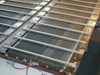
Rather than having them float, I would suggest bending them so they are routed to the outside surface of the stator frame where you can tack them in place with some hot melt glue or E6000. This is how Audiostatic does it. (see attached pic of ES-500 in the process of a rebuild)This is a good point which leads to a question.... I was thinking of just leaving the wires "inside" the frame such that they "float" at the top/bottom. With this, I would just recess the grids down into the frame rails such that the wires were flat with the frame. i.e. not run them over the frame ends. Is this a bad idea?
I regularly build test panels using 1/8” thick by 1/2” high crossbars made from 5-layer birch plywood. It is plenty strong. You can get 1/8”, 3/16”, and 1/4” thickness from local hobby stores, then all you have to do is rip it into 1/2” strips. Solid oak like CharlieM used is likely even stronger.I considered that but I really feel like I am pushing my luck with plywood at 1/4" in terms of strength. It is 1/2" "high" but still not sure I want to gamble with it is that thin. I would probably have to go the plastic route for something smaller.
Diffraction becomes a problem when obstacles or baffle discontinuities become larger than about 1/4 wavelength. I’m guess the low frequency diffraction you are talking about is the typical ripples around the baffle step in dynamic/box speakers. In the case of crossbars, they are obstacles that the sound waves from the diaphragm have to travel around. In the process, they will re-radiate at the outer edges. Basically each crossbar will re-radiate like a horizontal line source. The spaced sources will put ripples in the response which will shift around in frequency depending on the exact height of your ear or microphone. The thicker the crossbars, and the more closely they are spaced the stronger the ripples. Averaging response over a range of heights and the ripples go away, so perhaps they are not as big an audible problem as measurements indicate. Still, I like to minimize them as much as possible. Attached *.pdf is a few measurements I took some years ago comparing different crossbar thicknesses and spacings. I settled on 1/8” thickness as the point of diminishing returns. Oh, looks like on the last page I also have the impact on response of the light louver as used by Acoustat.I am no where near an expert but I thought diffraction effects are more of a problem in just the lower frequencies?
No adjustment to resistor values is needed for addition of vertical spacers.Thanks for the reassurance on the dispersion. I am mostly curious if I should be "tweaking" the resistor values for the segments surrounding the vertical spacers for better results.
Attachments
As Steve wisely says, " Averaging response over a range of heights and the ripples go away, so perhaps they are not as big an audible problem as measurements indicate."
For a dipole in a modern room (read: few stuffed furnishings) playing music, a lot of theoretical problems turn out to be imperceptible in practice.
For example, "beaming" looks absolutely terrible when you see a chart in a textbook. But that's a bird's eye view, not worm (er, I mean listener). All you hear at your seat is what comes to you. You don't hear a "beam". Given all the opportunities for fall-off of higher frequencies between the oboe player and your ear, no way to figure whether the treble component of that oboe sound is going to be too much or too little due to beaming.
And don't get me started ranting about the mistaken concern about comb filtering!!!
Ben
Last edited:
Wow... thanks Steve, for that info... let me think about all this a bit before I start asking questions 🙂.
It is hard to tell, but those Acoustat panels spacers look 3/8" ish in width 🙂
You should gather all this stuff up and write a book! I would buy it 🙂.
It is hard to tell, but those Acoustat panels spacers look 3/8" ish in width 🙂
You should gather all this stuff up and write a book! I would buy it 🙂.
Last edited:
Ummm, I think he's really thanking Steve, not my post that popped up in the middle time. As I would too.
B.
B.
Have a question about the resistor segments. I am using resistors in series for each of the segments. Is there any particular reason why the resistors in the series need to be close to each other in value? I ask because with the changes I've made I have a bunch of resistors that don't quite fit the original plan 🙂.
For example, for the 1st segment (the very center physical segment will not have any resistance, hooked directly up to the transformer output), I need a total of 44K. So I would have 3 9.1K + 3 5.6K (44.1K) resistors. I figure you wouldn't want to do anything really crazy like a 2 ohm + a number of kilohm resistors because the current thru the 2 ohm would probably make it catch on fire 🙂.
BTW this is what the calculations look like now:
1 ==> h: 48.00 (in) height
2 ==> w: 13.36 (in) width
3 ==> d: 0.0730 (in) gap
4 ==> r: 15.0000 (ft) distance
A: 0.4137 (m^2) area (panel)
h: 1.2192 (m) height
d: 0.0019 (m) gap
Vpol: 3,708 (VDC) Vbias (optimal)
Vsig: 7,417 (Vpeak) Vsignal (max/optimal)
5 ==> N: 11 # sections
6 ==> fL: 250.00 (Hz) LFbreak pt
fH: 121000.00 (Hz) HFbreak pt
R: 58.62 (Kohms) Feed Resistance
Ctot: 987.35 (pF) Cpanel
C: 89.76 (pF) Csection
w(sec): 1.21 (in) width section
30.33 (Vrms) input limit
7 ==> Vin: 28.00 (Vrms) amplifier voltage
8 ==> Step-Up: 150.0 step-up ratio
9 ==> Vbias 4,200.0 (VDC) bias voltage
10 ==> Line Source: Finite Type of Line Source
Vstators 4,200 (Vrms) stator-to-stator voltage
5,940 (Vpeak) stator-to-stator voltage
11 ==> Fs: 120.00 (Hz) Resonance Frequency
12 ==> Q: 10.0 Resonance Q
Since you are planning to use 6 resistors in series for each segment, there is no reason to can’t use an assortment of values to get the total that you need. Note that since they are in series they will all have the same current flowing thru them. The voltage across each individual resistor would then be V=IxR (ie voltage drop across each resistor is proportional to its resistance). So in the case of including a 2 ohm resistor in with a bunch of Kohm resistors, the current thru it would be based on the sum of all the resistances in series, not its 2 ohm value. The voltage drop across the 2 ohm would then be very small, so its power dissipation small as well.…Is there any particular reason why the resistors in the series need to be close to each other in value? …I figure you wouldn't want to do anything really crazy like a 2 ohm + a number of kilohm resistors because the current thru the 2 ohm would probably make it catch on fire
Are you talking about the Audiostatic (not Acoustat) aluminum cross bars that was shown in the first pic?It is hard to tell, but those Acoustat panels spacers look 3/8" ish in width
If so, I think they were 8mm on the smaller models and 10mm on larger. Using metal from cross bars is good from a strength perspective, able to span large distances with minimal thickness and height, giving a nice clean look to the panels. But, they form a bypass capacitance around the ladder resistors, undoing some of the segmentation that you are trying to implement to improve dispersion.
For more details see: http://www.diyaudio.com/forums/plan...ostatic-baffle-step-filter-4.html#post3385741
Since you are planning to use 6 resistors in series for each segment, there is no reason to can’t use an assortment of values to get the total that you need. Note that since they are in series they will all have the same current flowing thru them. The voltage across each individual resistor would then be V=IxR (ie voltage drop across each resistor is proportional to its resistance).
Yeah, duh, I knew that... brain wasn't working too well yesterday 🙂.
I am using Ken Seibert's boards so they start at 6 resistors then go to 5 then 4; then 3 for 4 segments then 2 for the last 5 segments (I only need 4).
BTW, they are 2 watt, 500V resistors.
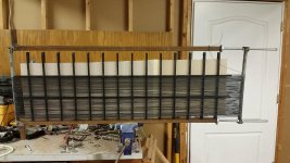
So got around to winding some wire over the weekend and thought I would share an update.
Attached are a couple of pictures of my winding jig about 2/3's wrapped.... the bad news is I ran into trouble when stretching.
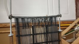
Apparently, 2 5/8" rods welded together are not strong enough by themselves to stretch this wide of a panel (my jig has about 16" inside width).... so to share in my fail 🙂......I've attached a picture showing it bowing quite a bit..... The net result was, the outside wires stretched nice and straight but the inside wires didn't even come close.
Rather than "unwinding" the jig, I am going to try and salvage the situation by gluing down the outside straight wires, cut them, then stretch the wires toward the center, glue them down etc.....
Once these 2 stators are removed from the jig, I will make a new end piece and it will be strong enough......
I should've known better but oh well, live and learn 🙂
Attached are a couple of pictures of my winding jig about 2/3's wrapped.... the bad news is I ran into trouble when stretching.
Apparently, 2 5/8" rods welded together are not strong enough by themselves to stretch this wide of a panel (my jig has about 16" inside width).... so to share in my fail 🙂......I've attached a picture showing it bowing quite a bit..... The net result was, the outside wires stretched nice and straight but the inside wires didn't even come close.
Rather than "unwinding" the jig, I am going to try and salvage the situation by gluing down the outside straight wires, cut them, then stretch the wires toward the center, glue them down etc.....
Once these 2 stators are removed from the jig, I will make a new end piece and it will be strong enough......
I should've known better but oh well, live and learn 🙂
Attachments
- Home
- Loudspeakers
- Planars & Exotics
- About to take the ESL plunge