Much easier would have been to have just googled some images.
Thank's you for the advice, never thought of using google. How do you do that?
ex: if each chip "sees" 12 ohms then figure 33 puts a bpa300 (6 chip) at pretty close to 180W using +/-28 (volts at full load). of course this does not account for mains variation etc.
this was meant to address the OP's 8 ohm load case -- he said: "if you enter 6 pcs of LM3886 paralleled into 8 ohms and with a power supply of +/- 24V into the Overture Design Guide then you get 160 W into 8 Ohm". [of course his speadsheet gave the wrong result]
bridged it "appears" as 4 ohms per side.
bpa-300 is 3 chips per side.
each "sees" 12 ohms, effectively. so:
ex: if each chip "sees" 12 ohms then figure 33 puts a bpa300 (6 chip) at pretty close to 180W using +/-28 (volts at full load). of course this does not account for mains variation etc.
Last edited:
I was referring to the 1st post of this thread, Mark.
well, then why did you quote a post that was not the first one?
the thread began with some statements about a jeff rowland design and a question about how to handle dc offsets on the cheap (which i answered, BTW).
since there were some errors in the first post a discussion on several of the design and performance factors with the amp ensued.
there were some initial unkind comments directed at people who were trying to help with various aspects of it (perhaps imperfectly).
since there were some errors in the first post a discussion on several of the design and performance factors with the amp ensued.
there were some initial unkind comments directed at people who were trying to help with various aspects of it (perhaps imperfectly).
Last edited:

Disrespectful posts deleted and points handed out. Keep it technical and argue it out accordingly.
initial unkind comments
You'll have to excuse me, us here are rather blunt.
I just don't understand why this talk of bridged or parallel continues to return, even after 15 years.
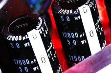
(even with the +/-28V rail voltage levels clearly printed on the amp board, at the test points near the central dual power bus bar)
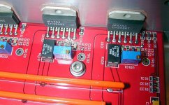
More interesting is how the 3886 chips are driven, why the four opamp front-end and the four 4.7uF MKP caps per side ?
Not just to rehash the spreadsheet again but could the spreadsheet be including dynamic power (crest factor) in its calculations? As far as those MKP caps go, my guess is that they're decoupling by their proximity to the chip. They also might be part of a Zobel but aren't they a little big for that?
If you want to use the spreadsheet for power calculations of parallel IC, fill in the data for ONE IC and the load impedance. For most practical uses the calculated voltage and power output will be correct. If you want to calculate for a BPA, fill in the data for ONE IC and half of the load impedance. The "bridge mode power calculation" will give you the total maximum power output. If you want to do the thermal calculations, first calculate the impedance as seen by each IC. The problem is that the spreadsheet is limited to 4, 6 and 8 Ohm and in the case of the JR amp for a 8 Ohm load, the IC sees 12 Ohm.
As far as those MKP caps go, my guess is that they're decoupling by their proximity to the chip. They also might be part of a Zobel but aren't they a little big for that?
The zobel (and output coil) is right before the output terminals, on the vertical positioned board at the back panel.
(again where it's visible that it's a BTL amp : Red wire for one output, Black wire for the opposite phase. The dual bus bar carries both phases, the outputs of IC1+IC3+IC5 are connected to one bar, IC2+IC4+IC6 to the second)
Why 4 caps ? And not 6, or 2.
Attachments
Last edited:
I took a look at the spreadsheet and it does require you to choose a fixed impedance so kudos on exposing this limitation. If he's using a coil on the output then it's Thiele, not Zobel. Those caps must then be used to balance the chips so they don't current hog and that's why you wouldn't need six. He probably put the caps (possibly in the form of a snubber) on the more eager chips to soak up some of the power output.
Last edited:
More interesting is how the 3886 chips are driven, why the four opamp front-end and the four 4.7uF MKP caps per side ?
this is the exact approach i have used for a xlr-trafo-input stereo end-to-end balanced chipamp design
i'm unsure of LR's reasons but i can tell you mine:
1- caps block xlr phantom power (prevents accidental saturation or destruction of trafo if some fool plugs in an xlr that has live phantom power.) to do this properly for end-to-end balanced stereo takes at least 4 caps
2- opamps help in 2 ways. a) cut off the chipamp's inverting feedback loop (so it does not inadvertently include the input interconnects and the output network of the source) if the topology is phase inverting b) present low impedance to the trafo (and chipamp) to improve linearity and/or low end performance
in the tube/valve design world that i mostly inhabit these are well understood issues, although in the tube/valve case i'd of course be using a tube instead of an opamp -- but with the same purposes in mind
so actually, given the topology, JR has taken a quite standard approach.
i'm surprised shine7.com didn't follow this aspect of the JR design more closely.
Last edited:
Likely didn't consider that the IC's may also be driven differentially.
(that makes 4 identical film capacitors, of 3.3uF-4.7uF value, and preferably MKP)
(that makes 4 identical film capacitors, of 3.3uF-4.7uF value, and preferably MKP)
oh i'd bet JR considered it and i definitely considered it as you will see conceptually (i say conceptually because they are tube/valve) in the schemtics linked belowLikely didn't consider that the IC's may also be driven differentially.
(that makes 4 identical film capacitors, of 3.3uF-4.7uF value, and preferably MKP)
but----
it actually depends.
i did take the capacitively-coupled-balanced buffer approach in the three xlr-balanced-bridged circuits that are toward the end of this pic:
https://drive.google.com/file/d/0Bz_iSmmoJEGTSGo2YVBnVHZxQlU/view?usp=sharing
but in an instrumentation-style design, having a differential buffer does not necessarily entail capacitive coupling.
there is quite a good thread here on that topic -- i'll see if i can find it.
Last edited:
Thanks Steve, these are the kind of refinements most diyers like me never even consider and that's why so much of what I make ends up in the recycle heap 🙁
Last edited:
Thanks Steve, these are the kind of refinements most diyers like me never even consider and that's why so much of what I make ends up in the recycle heap 🙁
commercial gear also often overlooks edge issues like these. it may be that their engineers don't think about all the crazy things that can go wrong (or maybe the bean counters tell them not to spend money on them).
Dear members,
I tried to find how adjust all trim pots on Shine7 solutionBPA300. What should be done to achieve the lowest DC on output ?
I tried to find some explanations on Intrenet, but there is no straight procedure to do it.
As you know there is 3 LMs and 3 trim pots, so what to do to receive famous 9 mV on output?
Sorry for stupid question, but I have to…
Thanks in advance, regards,
Boris
you adjust the pots before installing the load sharing output resistors.
set all six output offsets to be as near to equal as possible (and as close as possible to 0v).
i use a temporary 12R load on each chip output pin.
set all six output offsets to be as near to equal as possible (and as close as possible to 0v).
i use a temporary 12R load on each chip output pin.
The problem I see (I have never tried to build any of the multi-chip implementations) is that the output offset varies as the chip/s warm up.
You can set the output offsets to match when completely cold and watch them wander off and destroy the amp as the imbalance becomes too great for the output stage
or
you can set the output offsets to match after the chips have warmed up, then watch the amp destroy itself due to unmatched output currents during start up and the following warm up offset error.
A DC servoed amp that is "zeroed" when cold and uses the servo to maintain that "zero state" during warm up is in my view the right way, based on the FACT that National show a triple servoed version in the ap note.
Thank you all, but how position trims? To the lowest or the biggest value before powering up?
Nothing is the problem for me except adjustment. Always there are many questions, doubts, and opposite suggestions.
Is there any cookbook by Alex which can explain what to do and when?
Someone say desolder output resistor, others say no. Someone say measure on output pin number 3 but what to measure and what to set on this pin. We have 3 pins on eash board. Do I need to set 3 mV to achieve 9 mV in total or anything else?
Is there any potentional posibility of damage any of circuits if I apply wrong measure procedure?
Once again thanks to all, but I'm still blank.
Alex - please help me with BPA300.
Boris
- Status
- Not open for further replies.
- Home
- Amplifiers
- Chip Amps
- About the Jeff Rowland LM3886 amplifiers