If one chip can supply 22 Volts to a load. What is the maximum voltage that 2, 4 or 6 parallel chips supply?
The answer is 22 Volts. No need to do the maths. 2, 4 or X chips the answer stays the same.
If there is no increase of the voltage and the load stays the same, the maximum power also doesn't change.
Calculate the maximum power for one chip with the rail voltage and load impedance, if you have one chip or six the maximum power stays the same.
Last edited:
Please explain.
It's another way of saying you should think and read a datasheet before posting.
Try figure 33 in the 3886 datasheet.
That still doesn't get you near the claimed 160 watts into 8 ohms.
It is my lack of knowledge that is showing, or my attempt at over simplifying things.
It is my lack of knowledge that is showing, or my attempt at over simplifying things.
Last edited:
Wouldn't that calculation be for a 2 chip amp? IE PA100? I didn't run the numbers other than in the Overture Design Guide from National. It claims 160W into 8 ohm with 6 paralleled LM3886 with a +/- 24V supply.
jacco vermeulen said: "With Vs at +/-42V max loaded, ~40Vp, ~28.5V continuous, 100W/8"
but CJ900RR's above-quoted claim is the one being challenged +/- 24v not +/-42v
you should read the thread before posting
Last edited:
Isn't it sufficient that an LM3886 can handle only 42V rails, that's as simple as it can get.
A number of years ago, there were hi-res images of complete JRDG output stage originals on the web, which showed that half of the 3886 bank is driven differently. Or one could check out the amps interior visually oneself.
For some reason, 2kx1k pixel and higher images are rare these days.
But who cares, Mr Rowland used bridging in his Rowland Research stereo amps of the 1980s, does it again with his current discrete bipolar darlington output stage amps (see the model 525)
Same as for the bus bar routine, JR used soldered wire in his early designs, now fancy insulated dual ones, still the same deal.
read the thread before posting
Maybe you should read the last question before posting.
Then again, complete induction math states that if A < B, and B squared < C, then A squared < C is also true.
(they may likely teach that at university only)
Don't you hate it when people get on here and spew their opinions when they may or may not know what they are talking about?
Well, here's another one.
Whitney is right assuming the power supply doesn't sag, which it will but maybe not a lot. Since that sag is a squared term in the power out formula, it can make a significant difference. Audio power out is basically power supply minus sat drops (usually) squared, divided by load impedance, times .707 if you want rms.
I'm still of the opinion (another one) that hooking two or more "voltage source" outputs together (paralleling 3886 chips) is not wise at all. Their output impedances are measured in milliohms, and they each have huge amounts of feedback that will cause them to "tug-of-war" against each other if there's the slightest bit of gain difference at any frequency. The least they are likely to do is run hotter just because of noise differentials. I'd be using 0.1% resistors, and still feel foolish. Am I wrong about this somehow?
Bridging however is good if stability can be verified.
it's part of the no-good-deed-goes-unpunished paradox. Mark Whitney was simply using rough estimation in trying to get the OP to understand that there had to be something fundamentally wrong with the spreadsheet results for what was supposed to be 8 ohm load and +/-24v rails. despite the later on and silly +/-42v red herring, we now know that the spreadsheet's error was caused by its arbitrarily substituting another load instead of the 8 ohms the OP thought he was using.
Last edited:
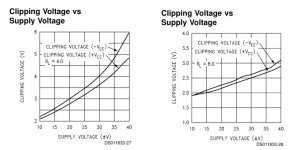
For those that missed it, Jacco is referring to a lower clipping voltage (higher output voltage before clipping) at higher load impedances. The datasheet does not state the clipping voltages for 16, 32 or 48 ohms, this leaves you guessing. A 6 chip 24 V parallel amp may squeeze an extra one Volt at the output compared to a single chip.
Last edited:
A 6 chip 24 V parallel amp may squeeze an extra one Volt at the output compared to a single chip.
And a 6-chip bridged amp with 24V rails can't do 150W in 8 ohm.
The datasheet does not state the clipping voltages for 16, 32 or 48 ohms, this leaves you guessing. A 6 chip 24 V parallel amp may squeeze an extra one Volt at the output compared to a single chip.
figure 33 expresses (for 20hz-20khz THD+N 0.1%) single chip output power vs load resistance at +/-28 and +/-35 so a reasonably accurate estimate is possible.
ex: if each chip "sees" 12 ohms then figure 33 puts a bpa300 (6 chip) at pretty close to 180W using +/-28 (volts at full load). of course this does not account for mains variation etc.
Last edited:
The part you're not considering is the load on the chips for 4 ohm use.
As a bridged design, three chips in parallel are looking at a 2 ohm impedance.
Returning to the original post of bridged or parallel : the model 12 (the monaural version of the 10) uses both sides of 6 chips.
The monaural model doesn't require the 12 chips total to reach the 200W continuous power in 8 ohm, but for the 350W/4 power figure. (is 175W continuous in 2 ohm for a bridged amp, see figure 33 again)
A 200W non-bridged power amplifier would require 60V rails minimum (power supply electrolytic caps would become 75V rated ones)
The power supply of the model 12 has a single toroidal with five electrolytic caps per rail, 12.000uF/50V types by Nichicon.
(the user manuals of the 10 and 12 clearly state fully balanced differential mode from input to output, btw. As the LM3886 is not completely differential, the power amps have to be BTL designs)
The bus bars used by JRDG are a standard product by Circuit Components Inc, btw. (H375-5-1.5-.5-FS type)
Two tin-plated alloy strips with a polyester insulating layer (0.25mm) inbetween, dipped in epoxy coating.
Last edited:
Each chip will see 6 Ohm impedance for a 6 chip into 4 Ohm load for a bpa configuration.
Or 12 Ohm with a 8 Ohm load connected.
Or 12 Ohm with a 8 Ohm load connected.
An amplifier that has fixed supply rails will deliver a particular voltage and it's commensurate current into a specified load.
The maximum Voltage is Vrail minus the amplifier loss. i.e. Vpk = Vcc - Vloss.
Vloss depends on the current passing through the amplifier. Change the load and the Vloss changes.
National's Clipping Voltage graphs show this.
Parallel a pair of identical amplifiers and the effective load seen by each amplifier is roughly half the actual load plus whatever balance improving resistors have been added.
Multi-paralleling of identical amplifiers achieve even more Vloss reduction, but again the balancing resistors add in their losses.
The overall effect of PA style (National's Parallel Amplifier topology) amplifiers is that there is an increase in Vpk less the Balancing Resistor loss resulting in a small increase in Vk and a small and almost insignificant increase in delivered power to the load.
The claim that Rowland can get 160W into 8ohms from parallel combinations of 68W into 8ohms amplifiers is simply impossible.
There is something else going on. Almost certainly Bridging combined with Paralleling, i.e. BPA style amplifying.
Last edited:
The claim that Rowland can get 160W into 8ohms from parallel combinations of 68W into 8ohms amplifiers is simply impossible.
Much easier would have been to have just googled some images.
The power supplies of the model 10/112 have the voltages printed at the locations where +/- power is taken off the board.
(red and blue wire that go to the umbilical connector on the back panel)
- Status
- Not open for further replies.
- Home
- Amplifiers
- Chip Amps
- About the Jeff Rowland LM3886 amplifiers