Not sure if it makes a difference but the 'different' 833 diagram is described as a functional block diagram, not a schematic as described in the earlier data sheet.
I see a completely different output stage there - so then does this suggest the original circuit in the DS I found was incorrect? I can't believe they would change the design down the road.
Digging around its looking more like TI are remarking MC33078s as LM833 - if you compare the two DSs I've yet to find any difference..... TI aren't telling anything about the internals of their version of MC33078 but I've attached OnSemi's - notice any similarity to TI's new LM833?
I said as much in post 52. I have seen variations of this output stage in a number of Motorola ICs - MC33171,MC34074,MC34080 in "Motorola Linear and Interface ICs" of 1985. The latter I have used in a preamplifier and I have a few left over for spares - it is no longer in production, however MC34074 is and it may help analysis to see how this differs from MC33078.
On Semi who took over from Motorola still make the MC34074, MC33078, and LM833 which is lower in the hierarchy toMC33078. ST Micro's LM833 is another premium chip based on the latter.
Not sure if it makes a difference but the 'different' 833 diagram is described as a functional block diagram, not a schematic as described in the earlier data sheet.
I did see that and imagine this hides a lot of the complexities for commercial reasons. However the output stage originally due to Motorola is said to be based on innovative concepts and the NPN output stage is inherently fast. Furthermore NPN transistors are used freely in the preceding and ancillary positions. There is only one ancillary PNP in the output stage.
In terms of the question whether it makes a difference, the manufacture of ICs is a competitive business and if not keeping abreast with developments you become uncompetitive. That other manufacturers have followed suit with the update speaks for itself.
<edit> there's one glaring error evident in this newer one - a MOSFET symbol is being shown (where there's bound to be really a JFET) in the biassing arrangement.
The must have put an intern on this job. Look at the schematic on page 1 under point 4 'Typical design exampl...'. The 2.2nF cap providing positive feedback is complete bonkers.
The national semiconductor 833 datasheet dated jan 2003 shows the complementary output stage.
The Ti 833 datasheet dated 2004 & revised may 2012 also shows the complementary output stage.
The Ti 833 datasheet dated july 2010 revised oct 2014 shows a quasi with NPN output stage.
The Ti MC datasheet dated 10 jun 2014 shows no sch/diag.
How confusing is this?
The Ti 833 datasheet dated 2004 & revised may 2012 also shows the complementary output stage.
The Ti 833 datasheet dated july 2010 revised oct 2014 shows a quasi with NPN output stage.
The Ti MC datasheet dated 10 jun 2014 shows no sch/diag.
How confusing is this?
My impression so far was that the 833 uses a complementary output stage while a quasicomp with tricky error correction/feedback and seemingly very low idle current is used in the (otherwise similar) 837. Would make sense with less die area available in the quad and self-heating being more of an issue. (I do think they were a little over-confident in the circuit when choosing idle current at the time. Typical '80s problem.)
The two different LM833 could be because both NatSemi and TI made LM833s, with one datasheet sourced from both when they merged.
The two different LM833 could be because both NatSemi and TI made LM833s, with one datasheet sourced from both when they merged.
But there are two datasheets.
Google take you to the TI datasheet dated 2012.
while post59 takes us to a different datasheet for supposedly the same device.
Google take you to the TI datasheet dated 2012.
while post59 takes us to a different datasheet for supposedly the same device.
I realized that much, but apparently didn't express myself clearly. One datasheet would have been inherited from NatSemi while the other would be for TI's own second-source part. Which one they are making now (or maybe both) is anyone's guess, ditto for what the difference in performance may be. Someone should compare the parts from both manufacturers themselves; Samuel Groner took measurements of both NatSemi LM833 and TI MC33078, so if one "LM833" is closer to the latter, one should be able to find that out.
TI's MC33078s arguably are better than the originals... but rebranding 'em as LM833 would not seem entirely appropriate.
TI's MC33078s arguably are better than the originals... but rebranding 'em as LM833 would not seem entirely appropriate.
The must have put an intern on this job. Look at the schematic on page 1 under point 4 'Typical design exampl...'. The 2.2nF cap providing positive feedback is complete bonkers.
The first op amp is configured as a unity gain low pass active filter of the voltage controlled voltage source variety.
Last edited:
I know what the circuit does so now I know the name for it. Mobile, can't look at schematic, so from what I gathered this morning: Firstly, there are better ways to create a low pass pole. This one depends on value of two caps to have straight fr before pole. Verified it with a quick sim, this particular combinatiom peaks before sloping down. Secondly, the cap between + and - input functions imo just like the resistor you would put there to increase noise gain in order to measure distortion below threshold of measurement equipment.
I know what the circuit does so now I know the name for it. Mobile, can't look at schematic, so from what I gathered this morning: Firstly, there are better ways to create a low pass pole. This one depends on value of two caps to have straight fr before pole. Verified it with a quick sim, this particular combinatiom peaks before sloping down. Secondly, the cap between + and - input functions imo just like the resistor you would put there to increase noise gain in order to measure distortion below threshold of measurement equipment.
The case in point is a 12 db/Octave low pass with a Q of 0.707. To be maximally flat within the pass band the 2n2 capacitor should be twice the value of the 1n one. It is not precisely so due to restricting capacitor selection for each unit to what is available within the standard value range.
I am aware that Bessel filters are preferred by many over the Butterworth ones.
I was so intrigued by all this that I took the question up with Texas Instruments who have been good enough to clarify matters somewhat.
It seems the original National Semiconductor device (the old LM833N, N denoting plastic package) is now the Texas branded LM833-N. This rebranding occurred after TI acquired NS. This device uses the NPN/PNP output stage we all know.
The LM833 was also 'second sourced' by Texas and is simply LM833. Now for the really interesting bit... this TI version does indeed use an NPN output stage.
All very very interesting methinks.
I was so intrigued by all this that I took the question up with Texas Instruments who have been good enough to clarify matters somewhat.
It seems the original National Semiconductor device (the old LM833N, N denoting plastic package) is now the Texas branded LM833-N. This rebranding occurred after TI acquired NS. This device uses the NPN/PNP output stage we all know.
The LM833 was also 'second sourced' by Texas and is simply LM833. Now for the really interesting bit... this TI version does indeed use an NPN output stage.
All very very interesting methinks.
Indeed, the phase splitter section and output resembles Linsley-Hood's 1996 Class A amplifier. It would be a challenge to modify this following in the steps of the IC designers.
And is it possible this two LM833's (with a complimentary and quasi complimentary output stage) to tell one from the other by their sound?
Or it is necessary to resort to more sophisticated methods, for example, to analyse their spectrum signatures (if complimentary and quasi complimentary output stages have some typical differs in distortion spectrum they produce)?
Or it is necessary to resort to more sophisticated methods, for example, to analyse their spectrum signatures (if complimentary and quasi complimentary output stages have some typical differs in distortion spectrum they produce)?
And is it possible this two LM833's (with a complimentary and quasi complimentary output stage) to tell one from the other by their sound?
Or it is necessary to resort to more sophisticated methods, for example, to analyse their spectrum signatures (if complimentary and quasi complimentary output stages have some typical differs in distortion spectrum they produce)?
🙂
I couldn't resist having a play. I ordered 5 of the SOIC outline... I have a nice little use for those upgrading the opamps in a Sony Mini Disc recorder. I also ordered 5 DIP outlines for a play as and when.
Attachments
Do we get to see comparison measurements/results on Tuesday?
I've been very pleased with the smd devices I fitted into the Sony MiniDisc recorder, but this cropped up today.
http://www.diyaudio.com/forums/chip...32-power-amp-thoughts-anyone.html#post4390787
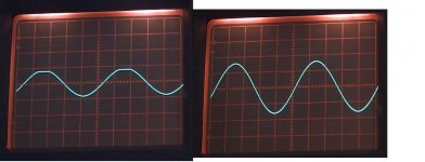
and this is the difference between the original 833 and the new quasi complementary offering. A remarkable difference in drive ability. Scope is on 5 volts/div
Attachments
- Status
- Not open for further replies.
- Home
- Amplifiers
- Solid State
- About op-amps use.