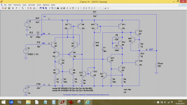
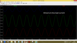
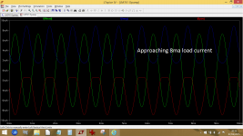
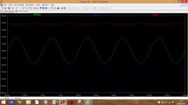
klystron (blame IE11 spell checker 😛)... that is quite an interesting measurement idea, in fact I was so intrigued I tried it in LTspice using a 741 biased at 2ma in the output stage. The supply current is 3.5ma per rail. For monitoring there are two 0.01 ohms, one in each rail. The diagrams show the current in the load and the two resistors used for monitoring. To increase load current I simply decreased the load impedance.
Very interesting.
(LTspice file attached as well)
Very interesting.
(LTspice file attached as well)
Attachments
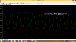
notice the visible 2nd harmonic in the supply rail currents in the middle pic ( approaching 4mA load current, is this = twice bias current?)
Hi Mooly! Thank you for reply.
I think you've got a good result, similar pictures I saw on my oscilloscope.
My result for AD843 (4 ma class A capability, hens 2 ma bias current) approximately corresponds to your middle picture.
Sure, the method is not accurate, been based on visual estimation of sine distortions (that item I started my post with). Nevertheless, it was useful for me, it turned out, the bias current was the small part of chip quiescent current, vice versa it takes place in ordinary (not chip) amplifiers and as I previously supposed.
By the way, is it really more easy to change load current changing the load, then the input signal level (I'm not guru in spice models, I use my own one's)?
(Excuse my poor French
 , I'll really do my utmost to improve it)
My best wishes Igor Shukov
I think you've got a good result, similar pictures I saw on my oscilloscope.
My result for AD843 (4 ma class A capability, hens 2 ma bias current) approximately corresponds to your middle picture.
Sure, the method is not accurate, been based on visual estimation of sine distortions (that item I started my post with). Nevertheless, it was useful for me, it turned out, the bias current was the small part of chip quiescent current, vice versa it takes place in ordinary (not chip) amplifiers and as I previously supposed.
By the way, is it really more easy to change load current changing the load, then the input signal level (I'm not guru in spice models, I use my own one's)?
(Excuse my poor French
My best wishes Igor Shukov
My result for AD843 (4 ma class A capability, hens 2 ma bias current) approximately corresponds to your middle picture.
It was an interesting little exercise and its always nice when simulation agrees with real measurement.
By the way, is it really more easy to change load current changing the load, then the input signal level (I'm not guru in spice models, I use my own one's)?
Erm... no special reason I did it that way other than hazy thinking that perhaps currents elsewhere could alter slightly if the level was altered. Decreasing the load seemed a safe way of pulling more current while all else remained the same.
(Excuse my poor French, I'll really do my utmost to improve it)
There are no problems from where I'm sitting 😉
Nice sim. Shows when class A stars to turns to B. You could have just shin the output emitter currents, almost the same thing.
"Decreasing the load seemed a safe way of pulling more current while all else remained the same."
Mooly, thank you much for the explanation. Yes, it's a good reason to alter the load current as you did.
Meanwhile, another suggestion occurred, how to enlarge chip class A capability.
May be simply to parallel similar chips in similar configuration (e.g. with the same gain) in order to summarise capabilities each of them?
It seems there is only one principle limitation - to have resistors (the same value) between a common output point and output of each chip.
In many practical applications (may be in most - headphone amps and etc.) such resistors are obligatory.
As to extra hardware expenditures - they don't mind much about it in Hi-End🙂.
May be somebody had experimented with OpAmp paralleling, how did it influence the sound?
Nice sim. Shows when class A stars to turns to B. You could have just shin the output emitter currents, almost the same thing.
Thanks 🙂
Also works on power amps.
Yes it does, I tried it on Doug Selfs 'blameless' and it worked as expected.
"Decreasing the load seemed a safe way of pulling more current while all else remained the same."
Mooly, thank you much for the explanation. Yes, it's a good reason to alter the load current as you did.
Meanwhile, another suggestion occurred, how to enlarge chip class A capability.
May be simply to parallel similar chips in similar configuration (e.g. with the same gain) in order to summarise capabilities each of them?
It seems there is only one principle limitation - to have resistors (the same value) between a common output point and output of each chip.
In many practical applications (may be in most - headphone amps and etc.) such resistors are obligatory.
As to extra hardware expenditures - they don't mind much about it in Hi-End🙂.
May be somebody had experimented with OpAmp paralleling, how did it influence the sound?
Doug Self has a 15 watt (rms) power amp made of 32 parallel 5532 opamps each with a 1 ohm series resistor to sum the output.
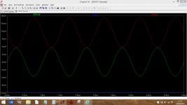
On the 741 sim we can do the old trick of adding a current source (or sink) from either rail to the output to force the stage into class A.
This shows the effect of a 10ma current injection, first from pos rail to output and then the neg rail to output. We are now delivering 6ma peak into the load while still essentially remaining in class A.
Attachments
Mooly, for a real 741 and lots of other OPamps up into the mid 80's the PNP output transistor was some form of a lateral PNP is far worse in every respect than it's NPN counterpart on the positive rail. Because of this, a pull-down is recommended rather than a pull-up. Keeping the amp in class A for all desirable loads then essentially shuts off the slow lateral PNP and you get a higher slew-rate (albeit overcompensated) 741. I used this trick literally decades ago and it makes the old 741 sound quite usable 🙂
It is also applicable to the 5532/5534 OPamp, which tends to sound better to my ears in this configuration.
While at the subject, assuming enough headroom from the power supply lines, adding an external simple complementary follower (suitably biassed) to the output of a 5532, so that the biasing network goes through the pulldown CCS for the NE5532 only (a red LED plus single 1N4148 in proximity to follower transistors will work great here) results in rather surprising performance from a 5532. It's well worth a try - connect red LED + 1N4148 from output of OPamp to negative rail through a CCS (give it some 4-5mA!), then NPN base for the follower directly to the OPamp output and base of PNP to the cathode bias string. A suitable cap across the bias string is a good idea. Use appropriate emitter resistors to bias the follower as needed. Enjoy 🙂
Some years ago the Australian Silicon Chip published a line preamp based around a pair of NE5532's. The same circuit has appeared in subsequent projects in more recent years.
The NE5532's were replaced by OPA2134 and LM4562 but the latest version (2011) uses LM833's.
The reason for this is that although LM4562 is better on paper their Audio Precision System One test equipment , "generally reports lower distortion when we substitute LM833 or NE5532 (the LM833 has slightly lower noise)."
I have been using ON Semiconductor MC33078 - having tried a variety of op.amps including NE5532, OPA2134, OPA2604, TL072, LF353, AD826.
By chance I was looking for some National Semiconductor application notes for LM833 and that took me to a new datasheet on Texas Instruments website. I recognized the circuit representation and the written description for this mirrored that for the MC33078 which is still sold by ON Semiconductor.
A feature of a good many op.amps from the latter is an all NPN output stage with no deadband distortion. In some respects it resembles a quasi complementary output with transposed halves driven by a phase splitter transistor. There is a driven current pull down section.
LM833's have an advantage in being readily available and relatively cheap. It has been noted that manufacturers have improved their processes. There has been a lot of dismissive comment about LM833's in the past - I say they are now worth another look.
Last edited:
Mooly, for a real 741 and lots of other OPamps up into the mid 80's the PNP output transistor was some form of a lateral PNP is far worse in every respect than it's NPN counterpart on the positive rail. Because of this, a pull-down is recommended rather than a pull-up.
Interesting info ilimzm. I must admit its a technique I've never given a fair hearing to. I did once try some constant current diodes + OPA134's but didn't draw any real conclusions from it all.
Great info though, thanks 🙂
By chance I was looking for some National Semiconductor application notes for LM833 and that took me to a new datasheet on Texas Instruments website.............................LM833's have an advantage in being readily available and relatively cheap. It has been noted that manufacturers have improved their processes. There has been a lot of dismissive comment about LM833's in the past - I say they are now worth another look.
Strange to say I came across the new data sheets and application notes for the LM833 as well. I've been refurbishing an ancient Philips spinner and I used new 833's here. As you say, very cheap now, under £0.40 here in one offs from recognised suppliers, in quantity much cheaper still.
LM833 is not bad at all, pretty good 1/f noise. Unless you need to drive a low impedance, it beats the NE5532.
Do you mean something like this? My doubt is CCS (C Current Source?)
Attachments
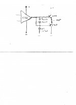
Do you mean something like this? My doubt is CCS (C Current Source?)
Yes, that's it.
Keep in mind that to get zero output, the OPamp output has to go positive to one half of the voltage of the bias string. This will make the circuit clip asymmetrically, so this should be taken into account for the actual device you want to use this with.
Here is an example - a DAC or CDP output. This is strictly limited to 0dBfs which is usually 2V RMS or 2.84V peak. If you use a high enough power supply (that would be around +-8V or more) the circuit will work just fine (*). There are however some CDPs that supply the NE5532 or equivalen OPamp on their output with +-5V and this is BARELY adequate unless the output is lightly loaded. This type of circuit will not work because it will clip on the positive side, and there may be more resons for it not working right (*).
(*) A CCS requires a minimum voltage across it to work well, so hanging a CCS from output of OPAmp to -V of OPamp is not as trivial as it may seem - one has to carefully chose the type of CCS depending on OPamp output voltage swing and -V power supply, or at extreme negative swing the CCS might stop working properly, so all ideas about keeping the OPamp output in class A fall down here. A particular case in pint are JFET based CCS or constant current diodes. These will start to resemble a rather low and non-linear impedance at low Vdg (even using Idss with G died to S directly), 'low' being anything from half a Volt to Vdss plus some volt(s) depending on CCS configuration. So, if you are planning on experimenting with an OPamp this way using a JFET CCS as as the simplest CCS form (because it's a 2-terminal device and easy to insert into a circuit), make sure the JFET has eonlugh voltage across it to really work as a half-decent CCS.
Do you mean something like this? My doubt is CCS (C Current Source?)
Re lateral PNP transistors - there was a case for preferring discrete component operational amplifiers in the days when design and manufacturing technologies were less than ideal in relation to today.
Problems with lateral PNP's were due to an inability to apply various masking layers with adequate precision.
40 years on this and diffusion technology has improved and ways have been found to avoid the use of PNP laterals where it might affect results.
The Texas Instruments LM833 has an all NPN output stage and apart from the absence of dead-band crossover distortion, it has symmetrical current source and sink characteristics, and an outside the box CCS is not advisable.
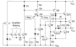
I can't see a reason for not using a CCS on the output of the LM833 - it looks to have the usual slow lateral PNP. Here's the schematic (from the TI DS) :
That is the original circuit given by National Semiconductor. Here is the link to Rev B from October 2014 http://www.ti.com/lit/ds/symlink/lm833.pdf the datasheet is long the circuit representation is on page 13.
I see a completely different output stage there - so then does this suggest the original circuit in the DS I found was incorrect? I can't believe they would change the design down the road.
<edit> there's one glaring error evident in this newer one - a MOSFET symbol is being shown (where there's bound to be really a JFET) in the biassing arrangement.
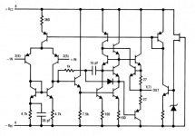
Digging around its looking more like TI are remarking MC33078s as LM833 - if you compare the two DSs I've yet to find any difference..... TI aren't telling anything about the internals of their version of MC33078 but I've attached OnSemi's - notice any similarity to TI's new LM833?
<edit> there's one glaring error evident in this newer one - a MOSFET symbol is being shown (where there's bound to be really a JFET) in the biassing arrangement.
Digging around its looking more like TI are remarking MC33078s as LM833 - if you compare the two DSs I've yet to find any difference..... TI aren't telling anything about the internals of their version of MC33078 but I've attached OnSemi's - notice any similarity to TI's new LM833?
Attachments
Last edited:
- Status
- Not open for further replies.
- Home
- Amplifiers
- Solid State
- About op-amps use.