the power supply is based L6599 this is a LLC power supply controller. Have a lot of other L6599 and they works great also from aliexpress.
Then you have choose a bad seller? Are these with feedback or without? because it is quite possible that the good working versions has
open loop who is better for audio amps seen the low idle current and working on the soft spot. But important is a startup delay otherwise it blows up
when charge the big caps. These caps are the solution for good impulse behavior, the LCC just works this way as a normal transformer, only a lot smaller.
Using feedback is a bad idea for these LLC versions, then you need LCC for better behavior on low loads.
https://www.ti.com/lit/an/sluaab9a/sluaab9a.pdf?ts=1696833460541

I see this one has feedback, just put a load on it and then switch the supply on. Then when the load is enough heavy you can see if it works properly. It seems there are bad ones on Ali lurking around or not suitable for audio amp purposes.
The left side on the driver pcb I see the feedback part, using a 431 I had some pcb from ali who has fake parts on it.
But I think you need to load it first for say 2 amps or so, and see what happens.
You can remove the feedback but need to adjust the frequency so you are in the power indepentent part of resonance plt.
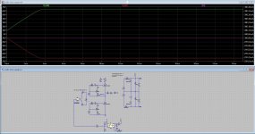
In the meanwhile before I go on with the rover p6 3500S I have simulate the supply for audio.
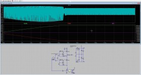
This one uses a very fast feedback, and with a zenerdiode only and a simple rc correction do very well until 300 mA, as the
most audio amps draw more the 300 mA idle current it is maybe a better way.
For me a open loop on resonance version is even better because can go lower, to maintain soft switch there is the need of a higher
freeloop current in the resonance parts, just enough to do well, so this is a little tricky..
The simulation afcourse is a test, not a working schematic but I think it is usable start. Please be careful, the voltages are lethal.
Attachments
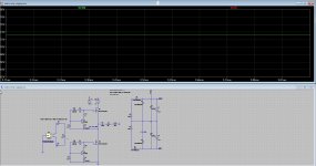
And here is the open loop, need to find the hotspot with minimum change voltage/current.
Here I get 66 volts 10 amp and 73 volts 0.3amp. I can even go better but haver no time left.
Not bad en also better for audio. So use the info, maybe it helps.
Here I get 66 volts 10 amp and 73 volts 0.3amp. I can even go better but haver no time left.
Not bad en also better for audio. So use the info, maybe it helps.
Attachments

- Home
- Amplifiers
- Power Supplies
- About Chinese LLC SMPS