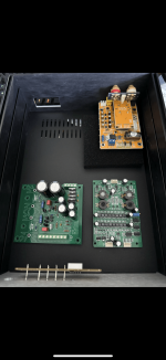
Some good progress on my Abbado build today!
I’m using the input board supplied by abraxalito
And the PSU is the a11 from AMB. The last of the parts to get it finished should be here Monday or Tuesday.
Can’t wait to fire this thing up!
I did have a view errors that I fixed in the FPD,
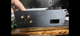
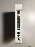
RCA cut outs are a little small so I’ll have to drill those out. I initially made the IEC connector cut out a bit short but I ended up finding one that would fit in the space.
More updates to come!
I’m using the input board supplied by abraxalito
And the PSU is the a11 from AMB. The last of the parts to get it finished should be here Monday or Tuesday.
Can’t wait to fire this thing up!
I did have a view errors that I fixed in the FPD,
RCA cut outs are a little small so I’ll have to drill those out. I initially made the IEC connector cut out a bit short but I ended up finding one that would fit in the space.
More updates to come!
Attachments


It is with much regret I will sell my Abbado 2 DACs, I have grown rather fond of them. It's those inductors...
Need to free up some funds so they are in the classifieds - https://www.diyaudio.com/community/...ian-r2r-discrete-nos-dac.414708/#post-7727033
Need to free up some funds so they are in the classifieds - https://www.diyaudio.com/community/...ian-r2r-discrete-nos-dac.414708/#post-7727033
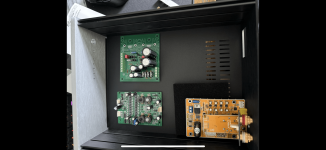
The Abbado II is fully assembled!

This was my first project where I had learn and use FDP (I used a Modushop GX288). I made a few mistakes from not paying attention but after some drilling, they all came out rather well!
Other than that everything came together extremely well. Wiring wasn’t bad besides the IEC. Due to a tight fit and a really crappy fuse holder the process was harder than it needed to be.
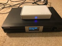
I think my favorite part is the front panel. Super clean and simple and you can’t beat the power up sequence:
No noise yet, waiting on four resistor to arrive so I can swap them out.
This was my first project where I had learn and use FDP (I used a Modushop GX288). I made a few mistakes from not paying attention but after some drilling, they all came out rather well!
Other than that everything came together extremely well. Wiring wasn’t bad besides the IEC. Due to a tight fit and a really crappy fuse holder the process was harder than it needed to be.
I think my favorite part is the front panel. Super clean and simple and you can’t beat the power up sequence:
No noise yet, waiting on four resistor to arrive so I can swap them out.
She sings today. I’m very happy with the finally version. Coming from an old beat up Yamaha receiver, the difference is incredible. Music sounds good again!
I’ll give it a few days of listen and give a more detailed listening review but as of now, sound is bright, big, and excellent!
I’ll give it a few days of listen and give a more detailed listening review but as of now, sound is bright, big, and excellent!
Can anyone give me the dimensions of the Abbado II pcb? Trying to figure out a chassis to put it in.
I did not build Abbado 2 but I was interested in it for some time. I inquired Abraxalito about his different DACs some time ago but at that time I have not decided to purchase any. A few weeks ago a Passive420 offered a fully populated board at a reasonable price and then I decided to go for it (too curious about those passive filters!!!). I have already a ESS Sabre DAC in a pretty large enclosure. For headphone listening with my laptop I carry around the house my laptop, head amp and the DAC. The small size of Abbado and the requirement to feed it with only one voltage made me think about a more "portable "DAC.
I was not going to post yet but since I have made remarks about Abbado 2 in a different thread I feel obliged to show what I have now.
As I said the board was fully populated. I have to admit that Passive's SMD soldering skills are a few orders of magnitude above mine (I have completed two EUVL's headphone amps and that was a challenge but I am getting better - a small soldering tip and small diameter solder helped a lot).
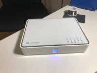
So I wanted a small housing for this DAC. This demanded an external laptop brick SMPS. I did not jump on it without any tests. So I tried a small 10V smps and linear PS with Elvee's denoiser. In fact I was impressed with the performance of a random cheap smps. So then I went for a laptop brick (3A) which I fed to the denoiser. That was pretty decent but not where I wanted to be, so I added LT3045 after the denoiser.
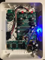
All this was too big for the old WiFi router box I had in mind for this DAC so I ordered a bigger box. The box has a long way to go from China so meanwhile I started tweaking what I had. I though maybe LT3045 does not need that great preregulation after all? Maybe just a plain LM317 would do - also to take some heat off LT3045. So I arranged the PCBs in the router box, cobbled a small regulator on a perf board and the pictures show where I am (last pic shows my two DACs - you will see what I mean by "portability"). Please forgive me long I2S cables(I know: keep your I2S cables short!!), I will replace them.
Did I mention that I like the sound of this little bugger very much. The sound is very neutral, analogue like. I am very impressed! The instruments have their own space, Very nice DAC.
I was not going to post yet but since I have made remarks about Abbado 2 in a different thread I feel obliged to show what I have now.
As I said the board was fully populated. I have to admit that Passive's SMD soldering skills are a few orders of magnitude above mine (I have completed two EUVL's headphone amps and that was a challenge but I am getting better - a small soldering tip and small diameter solder helped a lot).
So I wanted a small housing for this DAC. This demanded an external laptop brick SMPS. I did not jump on it without any tests. So I tried a small 10V smps and linear PS with Elvee's denoiser. In fact I was impressed with the performance of a random cheap smps. So then I went for a laptop brick (3A) which I fed to the denoiser. That was pretty decent but not where I wanted to be, so I added LT3045 after the denoiser.
All this was too big for the old WiFi router box I had in mind for this DAC so I ordered a bigger box. The box has a long way to go from China so meanwhile I started tweaking what I had. I though maybe LT3045 does not need that great preregulation after all? Maybe just a plain LM317 would do - also to take some heat off LT3045. So I arranged the PCBs in the router box, cobbled a small regulator on a perf board and the pictures show where I am (last pic shows my two DACs - you will see what I mean by "portability"). Please forgive me long I2S cables(I know: keep your I2S cables short!!), I will replace them.
Did I mention that I like the sound of this little bugger very much. The sound is very neutral, analogue like. I am very impressed! The instruments have their own space, Very nice DAC.
Attachments
Last edited:
Hi Greg - interesting story and background, thanks for sharing. I'm curious - as you've been a long-time user of an ESS DAC in the past, what does the Abbado bring to the party which the ESS lacks? Or put another way, what attracted you to the NOS/multibit sound?
There are a couple of things that might be able to be tweaked upwards. I note you've gone to great lengths to get low noise into the Abbado, with the Elvee denoiser and an LT3045. These regulators address what in EE jargon is called 'normal mode noise' or 'differential mode noise' which is noise of the power rail (+9V here) relative to the 0V. I feel sure they're doing a plenty good enough job at that. However there's another kind of noise which is called 'common mode noise' which is the noise on both +9V and 0V relative to mains earth. This kind of noise is introduced by switching bricks and once its in the system its very tricky to filter out. There are no 'common mode' regulators like there are differential mode ones. Common-mode noise is the reason I believe that switching supplies get a bad rap in audiophile circles and linears are considered the gold standard.
One way to mitigate common-mode (CM) noise is to feed the DAC's output into a balanced input (as normally found on an XLR), another is to isolate the DAC's output with a 1:1 signal transformer. A third method is a bit hit-or-miss and that's experiment with grounding the output of the switching supply so the noise currents don't flow through the DAC to the amp or preamp. I won't suggest swapping to a linear supply as a fix because you likely already have another source of CM noise - your laptop - at least when its running from its mains brick. The noise from that switcher will come down the USB cable into the DAC and then out again into your pre or amp via the screens of the RCA cables.
A second tweak is to upgrade the I/V resistors on Abbado to ones which introduce less low-frequency noise. I'll provide Mouser part links if you're interested in this.
Hi Richard,
Thank you for your extended reply. You are addressing exactly the issue I wanted to ask. You have already mentioned CM noise in the context of SMPS somewhere earlier in this thread when MJ filter was mentioned. When building my DAC I had your remarks at the back of my head. I still have a few questions. Forgive me if they are trivial (I am not an EE and my daily job is not EE related, though still pretty numerical).
One question is: can you use CM choke to address CM noise? I haven't done this a bit due to the space constraints and i did not like the idea of having power supply CM chokes close to the DAC passive filter inductors. Also I haven't seen anything on the scope, which is related to the next question:
I see how you get CM noise with a floating output of the smps. But my power plug is earthed. The earth pole seems to be connected to the negative output of the PS. Do you get CM noise in this case? If I observe the positive vs negative output of the PS with an oscilloscope I cannot see anything suspicious (my scope goes to 20MHz, not high enough? I would not say that). BTW I see something (ie DM noise) pre LT3045 but not after ;-) Am I measuring the wrong thing?
Why have I got interested in Abbado? Well having one head amp has not stopped me building another three, having a pre and power amp, speakers has not stopped me building more ;-)
But why Abbado? I do not think NOS was the main driver. I was attracted to a number of features: multiple paralleled DAC chips, passive filter and no opamps. I tried replacing opamp iv conversion (with great success) in some cheap Philips cd players with the Pass D1 circuit and Pedja Rodjic diamond buffer. I just wanted to try this.
How does it compare to the ESS DAC? I think I need more time to allow my initial emotions to cool down. I "think" ESS DAC sound (mind this is MY particular implementation!) a bit more HiFi while Abbado is more relaxed, nothing stands out. It very natural sounding. Having said that I think this points out some weaknesses of my ESS build - I did lots of tweaking there and it looks like everything matters. Opamps matter, PS of the analogue part of the chip matters, the PS of the digital voltage matters, opamps PS matters (at present I have separate LT3042 for AVCC and DVCC, with LM317 preregs. I have not separated L and R channel AVCC supply yet. Then there is Elvee's regulator for the opamps: OPA37 for iv and Burson Classic for the balanced to SE conversion). I guess I would like to try ESS with discrete iv conversion.
Regarding resistor upgrade. I think my upgrade kit is already on its way from Passive.
Greg,
You ask 'can you use a CM filter to address CM noise' and the answer is 'yes'. However in many cases it won't be particularly effective. Reason being - CM chokes work by increasing the impedance of the CM circuit thereby reducing the magnitude of the noise current. The impedance of a CM choke typically can get into 100s of kohm but only in a narrow frequency band (because the choke has a resonance with its stray capacitance). So if you're able to tune your CM choke to the switching frequency of your SMPSU you may get a decent attenuation of noise. But in the real-world that's not a highly practical suggestion (though not an impossible one) and so your choke might add 10k or so impedance. The reason that doesn't do much good is the CM circuit is already high impedance as the noise source is the SMPSU transformer and the noise gets out via that trafo's stray capacitance which is quite small (likely in the region of a few 10's of pF). 10pF of capacitance at say 80kHz switching frequency is an impedance of ~200kohm so you can see an additional 10k in that circuit will only reduce the noise current by 5%. You can of course use multiple CM chokes in series but that gets impractical pretty quickly.
If you earth the output of your SMPSU then you've provided a route for the noise current to return by, the amount of noise current that'll make it into your audio circuit will then depend on the relative impedance of the two circuits - the one to earth vs the one via your system. On first thought, the route to earth should be low impedance but given that no earths are perfect we have to take into account of the inductance of the earthing path. If that earth wire is a few metres in length we'll have an inductance of a few uH. If we're very optimistic you might have 5m of wire back to where mains earth is joined to mains neutral (I'm not an electrician so I'm not sure what's typical in a household installation). At 80kHz, 5uH has an impedance of 2.5ohm but the 80kHz is only the fundamental frequency so the harmonics will all see a higher impedance than that. With the earth connection you've exchanged a current noise source (because its high impedance) with a voltage noise source with a 6dB/8ve rising frequency response. In such a low impedance circuit a CM choke will do a good job of filtering, at least at the lower end of the frequency band. However if you have another connection to mains earth in the system then you may have created a low-frequency ground loop and find you've gotten mains hum that you now can't eliminate!
Looking for CM noise with a 'scope isn't likely to be successful as 'scopes have one terminal to mains earth anyway. So with a 'scope we can only measure relative to mains earth. What does work is a current transformer add-on to the 'scope, that provides isolation and allows noise currents to be seen. I don't have such a device though, so no experience to share of using one to track down CM noise.
Thanks for sharing what made Abbado seem interesting to you, that is useful feedback! OPA37 for I/V? I don't think I've heard of that before. Do you mean OP37 or maybe even OPA637?
Hi Richard,
Thank you very much for that answer. I kind of suspected that the length of the earth connection plays a role but your explanation goes so much further. I really appreciate that.
I will check the iv opamps. They are certainly not opa637. I think they are op37 then.
Thank you very much for that answer. I kind of suspected that the length of the earth connection plays a role but your explanation goes so much further. I really appreciate that.
I will check the iv opamps. They are certainly not opa637. I think they are op37 then.
Last edited:
Hi, next iteration of my Abbado II dac. Different usb adapter (Xingcore U30) and psu (Studer900 psu clone) Same output stage, Nelson Pass' B1 Nutube. Sound seems really nice!

Gaetano.
Gaetano.
Hi Gaetano - nice work there! As you're using an external buffer output stage you can bypass Abbado's output stage by taking the audio from the H1 connector in the middle (the two outer pins, middle is GND). You will still need coupling caps as there's DC present but the signal there is prior to Abbado's own buffer, direct from the I/V resistors.
I have also found quite recently that upgrading Abbado's I/V resistors (R37,R34,R68 & R47,R44,R42) to close-tolerance metal film makes a noticeable improvement to the background noise.
I have also found quite recently that upgrading Abbado's I/V resistors (R37,R34,R68 & R47,R44,R42) to close-tolerance metal film makes a noticeable improvement to the background noise.
"I have also found quite recently that upgrading Abbado's I/V resistors (R37,R34,R68 & R47,R44,R42) to close-tolerance metal film makes a noticeable improvement to the background noise."
Richard: are we talking Z-foil types SMDs, just run-of-the-mill 0.1% tolerance SMDs or matches values SMDs and what are their respective values?
Cheers, Pete
Richard: are we talking Z-foil types SMDs, just run-of-the-mill 0.1% tolerance SMDs or matches values SMDs and what are their respective values?
Cheers, Pete
Hi Pete - good question. I have yet to try out Z-foils on Abbado though I am planning to explore fancy resistor choices on my kDAC as that's the ultimate TDA1387 DAC. For Abbado I've just fitted 'run of the mill' 0.1% thin films (Panasonic, Susumu, Yageo) and gotten a nice lift in SQ. Turned out that even 'cooking grade' thick film can sound good if enough are used in parallel to share the load. I originally tried 10 or so paralleled thick film.
The values are 82R - 4 off and 330R - 2 off, all 0805s.
The values are 82R - 4 off and 330R - 2 off, all 0805s.
Thanks Richard, but I want to check something...you state "I/V resistors (R37,R34,R68 & R47,R44,R42)"..should that be R37,R34,R68 & R47,R44,R67 OR R37,R34,R32 & R47,R44,R42 ??
In the schematic I have, entitled "abbado II r1", the values of R37&47 are 6k2 and R34,44,67&68 are 56R and R32,42 are 1k5.
So, I'm a bit confused.
Thanks, Pete
In the schematic I have, entitled "abbado II r1", the values of R37&47 are 6k2 and R34,44,67&68 are 56R and R32,42 are 1k5.
So, I'm a bit confused.
Thanks, Pete
The r1 schematic doesn't reflect the current r2 Abbado II DAC resistor values. Yes I made a mistake in reading the silkscreen of an r2 PCB I have here, where I said 'R42' I should have typed 'R67'. Apologies for the confusion.
On your older r1 schematic the 6k2 shown is now 330R, the 56R are now 82R. R32,R42 aren't relevant to I/V duty.
Does that help lift the confusion?
On your older r1 schematic the 6k2 shown is now 330R, the 56R are now 82R. R32,R42 aren't relevant to I/V duty.
Does that help lift the confusion?
Yes,thanks for the clarification. Were there many other changes in values of components across the current r2 version, from the r1 version, that it would be beneficial to just buy the r2 version and make the resistor swaps?
Thanks, P
Thanks, P
Thank you Richard! Can you suggest me a suitable socket and plug to put in the H1 connector? Which pin is right and which is left? What cap value and type should I consider? In series?taking the audio from the H1 connector in the middle (the two outer pins, middle is GND). You will still need coupling caps as there's DC present but the signal there is prior to Abbado's own buffer, direct from the I/V resistors.
Many thanks again,
Gaetano.
- Home
- Vendor's Bazaar
- Abbado II NOS DAC kits