
@Freecrowder
Posts 1121 and 1123.
Best,
Anand.
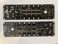
Here are some info files. for the sch and stuffing guide posted. hope its the same thing you want.
Posts 1121 and 1123.
Best,
Anand.
I am building a couple of integrated amps for my kids. My plan is to use the Hypex SMPS400A400 which will put out about 62V normally on 115VAC. I will run these at 36dB gain. I am using 2SB1560/2SD2390 outputs with .39 emitter resistors. I am listing the input section transistors to find out if there is something better to use.
For Q1, Q2, Q4 I plan to use BC546
For Q7 I plan to use BC556
For Q3, Q5 I plan to use TTC004B
For Q6 I plan to use TTA004B
Does anyone have better recommendations for readily available transistors for the input section?
For Q1, Q2, Q4 I plan to use BC546
For Q7 I plan to use BC556
For Q3, Q5 I plan to use TTC004B
For Q6 I plan to use TTA004B
Does anyone have better recommendations for readily available transistors for the input section?
I'm getting close to finishing my AB100. This version uses Pass boards (made possible by Nelson's generous contribution of Gerber files!), using the passive parts and diodes as specified in the original Pass schematic ( except C1, C2, C3 and C4), but with Qs (all sourced from Mouser) as follows:
Q1, Q2, Q4 are Onsemi BC639
Q7 is Onsemi BC640. (if you use this device on this board, watch out for part outline; "E" marking is correct, but part shape is reversed. Check schematic and board traces to make certain. See earlier posts in this thread.)
Q3, Q5, Q8 (bias) are Toshiba TTC004B
Q6 is Toshiba is TTA004B
Q9, Q10, Q11, Q12 are Onsemi MJ11016G (T0-3 Darlington)
Q13, Q14, Q15, Q16 are Onsemi MJ11015G (T0-3 Darlington)
On initial power up (after power supply tested fine months ago; +/- 50vdc) I could not get the either channel to work with a 500 ohm pot, per the schematic. Ramping up AC power on my variac, output Q bias across the emitter resister read 0vdc, until my DC power supply meter showed around 10vdc, at which point the Q bias reading shot instantly to 167mvdc, and I immediately shut down the variac. This was true for any output Q, NPN or PNP, and either channel.
I figured that maybe all my Q substitutions had resulted in a situation where the original 500 ohm pot value was just too low. So I took a hint from Osscar, and Prasi, and Wrenchone (and probably many others) and took out the 500 ohm pot and substituted a 5000 ohms multi-turn pot. I thought first of Osscar's example, since he used the same output T0-3 devices I am using, and I knew his amp works. As always, and as ZenMod recommended, I set the pot to max resistance, measured in situ, before beginning the bias adjust procedure. BTW: the max. R value the pot shows when measured in place on a stuffed board is less than its nominal max. value, due to other resistance in parallel, I assume
Bingo!! Problem solved! I ramped up the AC power with my variac, until my DC voltage meter showed both rails at 50vdc, and started reducing the new pot's R setting (Bourns 3299Y, 5000 ohm, multi-turn; avail. from Mouser). I stopped at Nelson's recommended 20mvdc bias setting, which remained stable, along with a respectably low DC offset reading of 5 to 10mvdc.
With a little more confidence, I next ran a very low level (well under 30mv) 1000hz sine wave through each channel of the unit from my oscillator, and captured the output signal from the amp's speaker terminals on my oscilloscope. The attached photos reflect the successful results, but don't begin to capture my joy!
The next step is to run some actual music through this amp and see what comes out. I figure if I have already gotten a nice sine wave through the amp, using test signals ranging from 1K to 10K ohms, I'll probably get some listenable music. But we shall see!
BTW - I apologize for the length of this post, but I figure the more detail the better, for the benefit of those other diy'ers who, like myself, can use some specific examples.
One thing I forgot to mention was the matter of gain setting for the AB100, as determined by R 3. My amp uses the originally specified 100 ohm value for this resistor. Several people have raised this value, in order to reduce the amp's gain, using 1000 ohm, or 750 ohms, or some indeterminate resistance designed to reduce gain to a desired level, from what I gather was originally something like 60X. Does anyone have any specific recommendations?
Given the fact that my output Qs are solder connected to the board, rather than attached by sockets, and given the way I have mounted the boards to the output Q brackets, I cannot easily access the underside of the board. It took me ages to replace the pots on my boards, working solely from the top of the boards, and trying to clear the component holes with solder sucker or braid. So exploring several iterations for R 3 empirically would be a real unsoldering chore. Can anyone tell me how to calculate gain value from the schematic and BOM, and maybe more importantly, give me an idea why lessening the gain would be worth the effort? Does the gain value affect ultimate power output of the amp into 8 or 4 ohms? Thanks in advance to anyone who can help.
Given the fact that my output Qs are solder connected to the board, rather than attached by sockets, and given the way I have mounted the boards to the output Q brackets, I cannot easily access the underside of the board. It took me ages to replace the pots on my boards, working solely from the top of the boards, and trying to clear the component holes with solder sucker or braid. So exploring several iterations for R 3 empirically would be a real unsoldering chore. Can anyone tell me how to calculate gain value from the schematic and BOM, and maybe more importantly, give me an idea why lessening the gain would be worth the effort? Does the gain value affect ultimate power output of the amp into 8 or 4 ohms? Thanks in advance to anyone who can help.
I just found an article in these forum pages on Gain Structure! I guess I better read that and see what I can glean from it.
https://www.diyaudio.com/community/threads/what-is-gain-structure.186018/latest
https://www.diyaudio.com/community/threads/what-is-gain-structure.186018/latest
here's my $0.02 - I tried original with 100R (gain of 36), then tried 475R (gain of 33), then 1000R (gain of 27) and finally settled on 750R (gain of 29) - for no other reason than I couldn't tell much difference in 475, 750 or 1000 so I just stopped experimenting - but I would say that with 100R there was a lot of gain in my system and I could get into clipping too fast. Didn't notice the sound changing - so may not matter a whole lot.
Thank you for your response, bullittstang! Clipping is something I would definitely like to avoid! If I understand what I just read in the gain structure article I cited above, it seems like setting gain levels in a system is dependent on what other circuits are in the system and what their respective signal levels are. And we are sort of (as the saying goes) "caught on the Horns of Dilemma": with one horn being the possibility of overdrive and clipping, and the other horn being a possible degradation of signal to noise ratio. Somewhere in the middle would appear to be the most desirable spot.
- Home
- Amplifiers
- Pass Labs
- AB100 Class AB Power Amplifier