Oh I agree. I had it running for probably 3 years now. It has its own sound compared to my other amps. I think it sounds much better than wheni first heard it.
So did your hum just develop or was is there all that time. In my build I did not have the HBR and the amp is dead quiet.
Well I think it was there all the time. Understand it was low enough that you couldn't hear it unless your ear was right up to speaker. So discovered REW and started taking hum measurements of all my amps. None could you hear at listening position but measured anywhere from -55 to -75 dB down. So I started on journey to .owerthe hum in all. So glad I did. I learned how to make my amps all very quiet. All -90 to-100 dB now.
Gary S. describes the correct orientation for Q7 relative to the Pass board silkscreen, as far as I can see. My photo in Post # 1,573 above shows how I soldered that part into the board. Note in the photo that the flat of the transistor faces the camera. The emitter pin is on the left (in agreement with the "E" letter silkscreen marking), but the silkscreen part outline shows the rounded side of the Q as the side closest to the camera, and is thus at odds with what I came to believe is the correct transistor orientation. In my own effort to solve the mystery, I looked at the circuit board traces from that hole marked "E" and made sure they went where they were supposed to go, according to the Pass schematic. I figured that identifying the emitter pin, and making sure it made connections consistent with the schematic, was more likely to indicate the correct part orientation than the flat vs rounded depiction in the silkscreen.

Exactly what I did after seeing the transistor outline silkscreen for Q7 differed from the other ZTX devices Q1,Q2 and Q4.
Last edited:
The R35 GBR value is indeed a handy degree of freedom for experimenting around the noise floor. Its optimum will largely depend on the overall grounding scheme of the entire system; the amp + source + TV (if any) + whatever else connected altogether. See also NP in #572. In my case it was the opposite effect with respect to yours: at the beginning I installed 10 Ohm and got a low noise floor which was only audible with ear on the tweeter but clearly present. After shorting R35 there is absolutely nothing, even at a centimeter away from the tweeter.Well I think it was there all the time. Understand it was low enough that you couldn't hear it unless your ear was right up to speaker. So discovered REW and started taking hum measurements of all my amps. None could you hear at listening position but measured anywhere from -55 to -75 dB down. So I started on journey to .owerthe hum in all. So glad I did. I learned how to make my amps all very quiet. All -90 to-100 dB now.
Another, similar observation was related to the AC power. My amp PSU is very basic: 600VA Toroidy with 4 x 36VAC secondaries, 4 active rectifiers, 2 x 22mF + 0.1uF per rail. I experimented with (1) untreated AC power, (2) DC blocking + passive noise filtering, (iii) DC blocking only. The last setting was a clear winner.
After optimizing the GBR and the AC power (and running in for about 50 hours) the amplifier sounds scary good over a dead silent background. It outperforms my last commercial pre + power amp combo (5k + 4k + Nordost Valhalla in between) at a massive margin. I am so happy that I built it.
Hi guys,to be more clear,please post the pcb version you have used together with the wrong print and the correction.
Dear Jim,
you can certainly have them all. I ordered the PCBs from JLCPCB which means I got the minimum 5 pieces while I only needed 2. Just PM your home address to me and I will attach the gerbers and dispatch the two boards next week. I would charge you what they costed me + shipping from CH to UK.
The SMA input is clearly a luxury here but I like it because of the ease of function generator connection, relatively small footprint, (very) broad-band transmission and also because the coaxial cabling of the input signal between the in-house power- and preamp boards cannot do any harm while flying over 230VAC parts, toroids and other potential noise sources. Probably not the most economical solution for OEMs but for our one and only PassAB100, why not?
Best,
Miklos
All right, there you go. 🙂 My version of the amp is very stable at 20-25mA bias per Sanken output transistor (+/-50V rails, Re = 0R47) while the heatsinks stay cool. However, please keep in mind that I am just a DIY enthusiast, NOT an audio engineer, so make fire with my layout at your own risk... 🙂
Attachments
Nelson's gerber files are in post #463, Insert Q7 opposite to silk screen transistor outline.Hi guys,to be more clear,please post the pcb version you have used together with the wrong print and the correction.
prasi's gerber files are in post #812
Another gerber file by member domyboy are in post #481.
I think there are a couple of other member's gerber files in the thread as well.
As Nelson points out in a post, this amplifier appeared as a commercial product built by 2 manufacturers using this NP design in the past and was reviewed by Stereophile for one of those.
The heavier you bias it the better it sounds.
Last edited:
Mine is currently biased at 40mV across the 1R0 emitter resistors (=40mA per transistor). The heatsinks are only moderately warm, so I could go higher. I used Sanken output darlingtons as well.
Now as the amp has been on duty for a couple of weeks (and has totally spoiled me) I took a few more snapshots, which I would like to I share with you as a teaser. The chassis is based on a 350 mm deep Slimline 2U from Gianluca but I added the 300 x 80 x 40 heat sinks and the CNC-made raw aluminum insert behind the face plate. Before you ask, I am afraid that the local manufacturer of the ceramic ball coupled feet has - most unfortunately - closed the shop during Covid.
Attachments
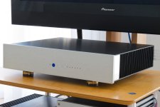
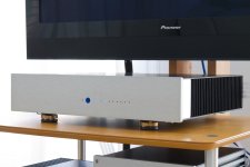
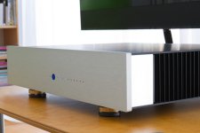
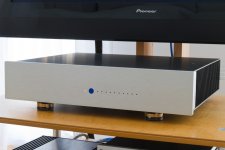
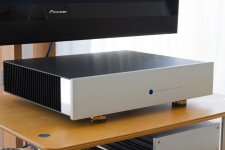
Very nice. Raw aluminum. Is that the cheeks on the side? And the stock silver faceplate with some mods? Like some info how you added the HS? It didn't come with them correct?
- Home
- Amplifiers
- Pass Labs
- AB100 Class AB Power Amplifier