Yes, the noise level is very low, if you put it in a shielded case - it will be even lower.One more thing: I compared the noise of the AB100 vs Audiolab 6000A amplifiers, with my ear to the tweeter. AB100 is in this parameter about 2 classes better. (almost nothing can be heard)
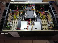

What power transformer + main filtration are you using?This was my build, a really great sounding and very solid amp. Thanks Mr Pass for the design and osscar for the help. !!
I've finished AB100 for now, I'm going to start Q17 with FQA46N15/FQA36P15 and which one I like the sound of I'm going to put in the chassis, ...
HRDSTL: do you replace the original output Darlingtons by the MOSFETs 'just like that' or do you modify something else in the circuit accordingly? How many pairs do you use at what rail voltage? What is the bias current per MOSFET? What are the specification requirements against the MOSFETs? SOA compatibility is obvious and I also see people arguing for lateral type MOSFETs here and there for low-bias AB purposes (without giving an explanation). Is there anything else? Thanks, Miklos
Yes, Q17 refers to a different amplifier.
https://www.diyaudio.com/community/...hile-approach-to-perfect-sound.374507/page-78
https://www.diyaudio.com/community/...hile-approach-to-perfect-sound.374507/page-78
I’ve been reading about optimal biasing points for bipolar output stages in Class AB…if the goal is just lowest overall THD. I admittedly have not looked at harmonic spectra info.
The consensus amongst some of the cogniescenti is to measure 22mV across the emitter resistor. This is irrespective of the emitter resistor value. As such, values at or near 1 ohm would be biased at around 22mA per BJT. And for values considerably lower, i.e. 0.22 ohms, bias would be 100mA per BJT transistor. The advantage with larger emitter resistors seems to be more stable bias current. The advantage with smaller emitter resistors seems to be lower distortion (but the BJT devices have to be more closely matched).
I’m curious with regards to Papa’s perspective (as well the rest of you reading) on this given that he has tremendous experience especially with his Threshold designs.
This is a stark difference for me compared to vertical MOSFETS where I would just crank the bias as much as my heatsinks could handle.
Is it true that overall THD can INCREASE at higher bias (but only at higher amplitude levels) with BJT complementary output stages such as the AB100? However, if the output transistors are tightly matched, will one be able to do away with the emitter resistors (or use small values), as such bias currents can be cranked much higher?
Thanks again for the enlightenment,
Anand.
Lots of people worship Barney Oliver's technical paper in the Hewlett-Packard Technical Journal. Worship it without bothering to read it.
Bob Cordell's book takes a somewhat more nuanced view: Oliver was a good man and Oliver had a good idea ... but ... we now have better equipment and better mathematical models.
Douglas Self's book, I will let you read for yourself. It seems muddled to me. Maybe Self's writing is crystal clear and my reading of it is muddled.
Both of them talk about Barney Oliver, GENUFLECT GENUFLECT, twenty-something-millivolts, yadda yadda; but what they say afterwards is very different.
Attachments
We recently had a long discussion on my article. https://www.diyaudio.com/community/threads/class-ab-biasing-article.393566
Distortion increases with overbias because the voltage drop across the emitter resistors is an error term - it goes from zero to some maximum on every cycle in class AB. More bias = greater error. Only when the bias is made so high that the voltage error becomes a small percentage of the signal amplitude at which cut-off occurs does distortion fall. This is where MOSFET amplifiers operate. Bipolar transistors can operate that way too.
Ed
Last edited:
How can a ZTX450 in the Q2 position survive '+/-50V or so' rail voltages? According to its datasheet, the absolute maximum collector-emitter voltage is 45V. I assume the emitter of Q2 is slightly below zero potential, otherwise the zero-offset signal at its base could not open it. But this means that the collector-emitter voltage on Q2 is >50V. Where am I wrong? Can anyone tell some relevant numbers from simulations or measurements, please? Thanks, Miklos
as with any differential input
assume the constant current source gets in the way.
or use 2n5551 / KSC1845 if it make you more comfortable
assume the constant current source gets in the way.
or use 2n5551 / KSC1845 if it make you more comfortable
- Home
- Amplifiers
- Pass Labs
- AB100 Class AB Power Amplifier