However, if you run the amp into clipping intentionally or accidentally (say your preamp sends a transient down to AB100, or you connect a cable while the amp is on), there may be a problem.
I'm sure you are right. I did briefly, probably less than a minute, clip both channels when testing the output. But during normal listening I doubt I'm using more than a few watts so I expect the transistors will last for me.


I love Toroidy transformers! I mostly only buy this brand nowadays. Very reliable and silent operation under load.
Do
Do
this transformer has 2 of 2x35V?This is a strange thing to say, but this is a really nice looking transformer!
How much was this shipped to you?
Thanks
this transformer has 2 of 2x35V?
How much was this shipped to you?
Thanks
Audio grade transformers:
TS 600VA PRI: 2x115V SEC: 4x 35V (4,28A) - cost: 92,10 EUR/pc (0% VAT export price).
Our offer is valid for the 30 days.
In audio grade, noiseless transformer price You'll get transformer winded with with the largest possible inductance.
Core will be measured and selected, nominal induction will be lowered for the leakage flux minimalization
For a best noise reduction core and all the windings are impregnated.
Transformer will also has electric and electromagnetic shields and epoxy filled interior.
Shipping cost to Canada - 52,00 EUR.
----
About $220 CDN or $170 USD, not cheap, but not totally unreasonable either.
The actual value is more like 1.3 X for about 40V, so you're extra safe.

generally tfr manufacturers take sag into account and no load voltage will be higher by 5 to 10%, + we also need to take care of mains variation of 10% or so in developing countries.. So 30 to 32 vac trafo will be probably safe in all respects.
generally tfr manufacturers take sag into account and no load voltage will be higher by 5 to 10%, + we also need to take care of mains variation of 10% or so in developing countries.. So 30 to 32 vac trafo will be probably safe in all respects.
I hope that 35v won't be too much... 😱
You can always set up a CRC to sap some voltage out. Better to have too much to start than not enough. 🙂
"Bias Current: about 0.08 A per channel", 1 Ohm means 0.08 V drop.
CRC works better on class A.
CRC works better on class A.
As Nelson says, bias is 80mA per channel, so divide by 4 output devices per rail = 20mA per 1 ohm emitter resistor, which corresponds to 20mV drop across each 1 ohm resistor.
what would be the optimal case for this amp in terms of heat dissipation?
That depends I guess on how hard you run the amplifier! I would suspect a nice 2u / 3u from the diyaudio.com store would work.
Does anyone have a recommendation for hFE ranges for the input transistors? I'm planning on using the Prasi board with BC547 for T1,T2, and T4 as well as BC557 for T7. Both transistors from ON/Fairchild are available in hFE ranges of 110-220 (A), 200-450 (B), and 420-800 (C).
Is it crucial to match the gain of the input transistors?
Thanks,
Sam
Is it crucial to match the gain of the input transistors?
Thanks,
Sam
the hfe numbers of the b-type are in the range of the original ztx450 (the c-type could also be used if you match these),
but take care of the pin layout..........
you can use the hfe-tester on your dmm to match the gain of the input transistors...........
but take care of the pin layout..........
you can use the hfe-tester on your dmm to match the gain of the input transistors...........
Yes it is quite enough to select input transistors with a multimeter or cheap LCR digital meter with equal Hfe... I got a 11mV and 2 mV at the output with 1% tolerance resistors.
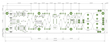
Gerbers for another AB100 PCB
Attached is the set of gerbers for my version of AB100 boards.
The layout quite closely follows that of Nelson Pass (post #463), I just added mounting holes conforming to the diyAudioStore's Universal Mounting Specification. One would need a heatsink about 100mm tall (wide) to be able to mount the output transistors on both sides of the PCB.
These boards have been built and tested - see post #1020 above for the picture of assembled board of a heatsink. They work as intended, and BTW, I still have a pair of extra boards left.
Thank you Mr. Pass for publishing both the schematic and the PCB - there are neat tricks I learned from both! Happy New Year!
Attachments
Attached is the set of gerbers for my version of AB100 boards.
The layout quite closely follows that of Nelson Pass (post #463), I just added mounting holes conforming to the diyAudioStore's Universal Mounting Specification. One would need a heatsink about 100mm tall (wide) to be able to mount the output transistors on both sides of the PCB.
These boards have been built and tested - see post #1020 above for the picture of assembled board of a heatsink. They work as intended, and BTW, I still have a pair of extra boards left.
Thank you Mr. Pass for publishing both the schematic and the PCB - there are neat tricks I learned from both! Happy New Year!
Nice board Layout Alex, Ever thought about doing some SMD verions ? Could make the board smaller ? Melf 0204 and Melf 0207 Etc etc.. Dual layer, thicker copper pours..
Thank you.
SMT is certainly possible - I have done this for other amplifiers - but to make AB100 much more compact there would need to be changes in the layout of the output stage. I wanted to keep the board compatible with the pre-drilled heatsinks from diyAudioStore, but if you throw that out, many interesting things can be done.
In the new year, perhaps
I will try to create a version, that is wider and not so long. Want to make two monoblocks with this design and it would be better, if i can use heatsinks on both sides. Only 4 transistors on each heatsink. Hope i find the time in the next weeks...
Thanks guys. I'm now thinking I'll use Nelson's pcb with ZTX450/550.
Any thoughts on dealing with inrush current? I've considered the store's soft start or Mark Johnson's version. Could a simpler solution just be thermistors like how it's done in Nelson's class a amps?
I'm planning to use a 500VA transformer.
Any thoughts on dealing with inrush current? I've considered the store's soft start or Mark Johnson's version. Could a simpler solution just be thermistors like how it's done in Nelson's class a amps?
I'm planning to use a 500VA transformer.
- Home
- Amplifiers
- Pass Labs
- AB100 Class AB Power Amplifier