My petulant exercise in amp layout may bear more fruit than I expect, as the layout is readily adaptable for other purposes. I've already spun off a version with mosfet input and lateral outputs. Before I proceed much further, I want to do some simulations to see if the compensation scheme I've chosen is actually sensible...
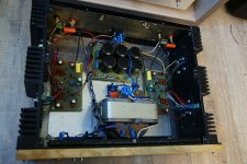
Amp ha been completed and it sings like crazy 😀
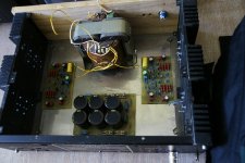
Everything worked even without test boards. No hum, dc offset 2mV and 10mV per channel.
Bias 40mA per transistor - runs cool.
no turn on/off thumps.
PSU - +- 45V 30 000Uf in each rail.
indicator diode foe each rail.
Transistors - ztx450,550,MJ340/350, mj11016/15.
0,5 ohm emitter resistors and base stopper divided-100R on PCB and 100 on transistor base pin.
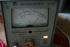
I will measure later with scope and sound-card - now I am a little tired after amp hobby work 🙄
Everything worked even without test boards. No hum, dc offset 2mV and 10mV per channel.
Bias 40mA per transistor - runs cool.
no turn on/off thumps.
PSU - +- 45V 30 000Uf in each rail.
indicator diode foe each rail.
Transistors - ztx450,550,MJ340/350, mj11016/15.
0,5 ohm emitter resistors and base stopper divided-100R on PCB and 100 on transistor base pin.
I will measure later with scope and sound-card - now I am a little tired after amp hobby work 🙄
Attachments

Amp ha been completed and it sings like crazy 😀
Everything worked even without test boards. No hum, dc offset 2mV and 10mV per channel.
Bias 40mA per transistor - runs cool.
no turn on/off thumps.
PSU - +- 45V 30 000Uf in each rail.
indicator diode foe each rail.
Transistors - ztx450,550,MJ340/350, mj11016/15.
0,5 ohm emitter resistors and base stopper divided-100R on PCB and 100 on transistor base pin.
I will measure later with scope and sound-card - now I am a little tired after amp hobby work 🙄
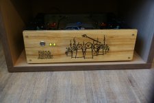
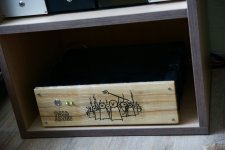
I love the front panel. How did you do it?
hi,
I transfer with iron - image printed on ebay PCB transfer paper with laser printer. After image transferring i varnish it (few layers).
I transfer with iron - image printed on ebay PCB transfer paper with laser printer. After image transferring i varnish it (few layers).

A laser-etched wood front panel might also be interesting... I wonder if the people that do this can work from image files?
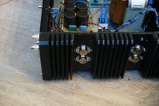
Yesterday I raised bias to 100mA per transistor - the massive heatsinks temperature after 5 h was reached 35C only (ambient - 22 C). bias is very stable as amplifier itself - i tested it with two way speakers and fullrange without crossover. Today i will measur amp preformance with scope and soundcard.
Well, you certainly have the First Watt covered, and then some. I try to bias for at least 1W of Class A operation in my AB designs, even if it means extra heat. Papa knows best...
I will try 1W bias 😀
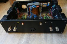
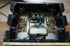
20Khz square scope shot and output power - output power of about 28V rms @ 8R/98W with 43V rails. I also installed fuse holder covers and painted enclosure lid in black.
20Khz square scope shot and output power - output power of about 28V rms @ 8R/98W with 43V rails. I also installed fuse holder covers and painted enclosure lid in black.
Attachments

Since you have a push-pull output, 1W RMS of class A bias would amount to a total bias current of about 0.25 A, or 62.5 mA per output device. Since you're far in excess of that, you've got a lot more class A headroom (~2.5 W RMS). I'd leave the bias where it is if there are no other problems.
Here comes i time that i prove my self wrong and right at the same time
Wrong since a commercial that features more than one pair of darlingtons exist in the market actually just showed up in the shop today for repair .
Right because this amplifier was totally blown for the known reasons ( i expect ) but i will look into it and get back to you .
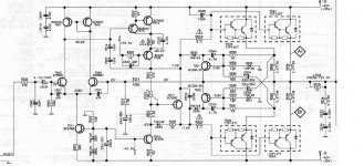
In between enjoy the schematic ....This is a commercial design existing in the market for a number of years and also features a patch of 150Pf in the upper side Only ! relatively low next to known other schematic . It could be also interesting to see how the amplifier will perform with and without the patch
Since i am way too busy and constructing the AB 100 will take some time I will grab the opportunity and measure and listen to this amplifier after repaired since i think its a look alike .
I will enjoy working with Tip 142-147 after 20 some years passed from the time i was blowing a few .
Wrong since a commercial that features more than one pair of darlingtons exist in the market actually just showed up in the shop today for repair .
Right because this amplifier was totally blown for the known reasons ( i expect ) but i will look into it and get back to you .
In between enjoy the schematic ....This is a commercial design existing in the market for a number of years and also features a patch of 150Pf in the upper side Only ! relatively low next to known other schematic . It could be also interesting to see how the amplifier will perform with and without the patch
Since i am way too busy and constructing the AB 100 will take some time I will grab the opportunity and measure and listen to this amplifier after repaired since i think its a look alike .
I will enjoy working with Tip 142-147 after 20 some years passed from the time i was blowing a few .
Attachments
Last edited:
Wrong since a commercial that features more than one pair of darlingtons exist in the market
Audio Analogue Puccini is very popular.
Audio Analogue Puccini is very popular.
Can you post a compete model ?
Can you post a compete model ?
Just google it i think it will come up on top.
very fine ....
That is the second one lucky also to see that this one also does work without patches .
This is weird since this worth farther investigation
What other people did that their circuit required patches ?
how other designers manage without them ?
I think the repair of the amplifier i have on bench will reveal more secrets
Let see
I found the Puccini schematic on the web - it uses a boosted opamp topology with the NE5534 and a single set of output Darlingtons. I did my own version using current mirrors that simulates pretty well, with an LF411 in the front end, as that was a model I had. If I actually built something like that, I might get all fancy-pants and use an OPA627 instead. All these designs benefit by loading in as much Class A bias as the traffic will bear, with considerations of heat and stability in mind.
- Home
- Amplifiers
- Pass Labs
- AB100 Class AB Power Amplifier