Coulomb said:On a side note this is the switch I just ordered for my Front Panels.
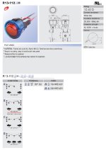
The units I ordered have a black cap not a red one. The blue ring iluminates in a glowing blue aura.
Contacts rated as 16A @125VAC or 10A @250VAC
Click on image, you may get a cursor to click on to enlarge to full size for better image.
Anthony
If anyone else is interested in this switch I will order them and include them in the kits for $5 if I buy 50, or they can be orders here.
Mouser
Anthony
Attachments
Anthony
These heatsinks look promising.
The drawing you made for the tapping, the hole aren't symmetric, you can't used the heatsinks upside down or left-right.
For the switch, have you look for Bulgin, they have some nice metal illuminated push button.
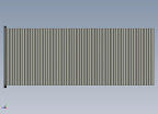
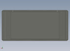
I made a preliminary drawing with 6 pairs of heatsinks and 3 top/bottom panels. You can customized it for 1 or 2 pairs of heatsinks with shorter "L" brackets.
Here some preview.
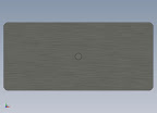
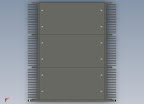
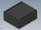
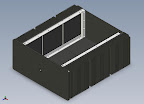
I attached a eDrawings file if anyone want to play with it.
(You must install eDrawings Viewer)
These heatsinks look promising.
The drawing you made for the tapping, the hole aren't symmetric, you can't used the heatsinks upside down or left-right.
For the switch, have you look for Bulgin, they have some nice metal illuminated push button.
I made a preliminary drawing with 6 pairs of heatsinks and 3 top/bottom panels. You can customized it for 1 or 2 pairs of heatsinks with shorter "L" brackets.
Here some preview.
I attached a eDrawings file if anyone want to play with it.
(You must install eDrawings Viewer)
Attachments
Anthony,
Thanks again for putting this together and expending the effort here.
Re: Switch
I for one generally prefer the power switch intergral to the power entry module to simplify things, especially on these amps which will likely not be sitting in a rack for most people due to air flow concerns. My vote would be for a blank front panel, allowing those of us who want to drill for LEDs/switches to do so.
That being said, this is not a deal breaker. Chartal's renderings look very nice, but I only need two per side🙂
Thanks
I am not sure I understand the thread - I mean, I am planning to build the F5 (from the cviller GB) and would at least like to pick up appropriate heatsinks (and a whole case would be okay too I suppose) and am in canada...does this GB fit the bill?
thanks for the help...
b
thanks for the help...
b
mantisory said:I am not sure I understand the thread - I mean, I am planning to build the F5 (from the cviller GB) and would at least like to pick up appropriate heatsinks (and a whole case would be okay too I suppose) and am in canada...does this GB fit the bill?
thanks for the help...
b
Yes by all means
Anthony
Chartal said:Anthony
These heatsinks look promising.
The drawing you made for the tapping, the hole aren't symmetric, you can't used the heatsinks upside down or left-right.
For the switch, have you look for Bulgin, they have some nice metal illuminated push button.
I made a preliminary drawing with 6 pairs of heatsinks and 3 top/bottom panels. You can customized it for 1 or 2 pairs of heatsinks with shorter "L" brackets.
Here some preview.
I attached a eDrawings file if anyone want to play with it.
(You must install eDrawings Viewer)
Hello Chartel, actually the screw hole locations are symmetrical for side by side use. The Heatsink can not be turned upside down and can only be used one way or else machining errors will cause a cosmetic defect in a visible area. did you read the whole thread?
Please explain why you think they are not symetrical.
BTW due to the stress exerted on the frame as it floats off the base with out the front and back plates bolted in, L brackets would bend in as the material at the junction is only 1/8" thick.
I am using 1/2" stock so the chassis can be worked on without relying on both front and back plates being in place.
Anthony
04dgmsilv said:Anthony,
Thanks again for putting this together and expending the effort here.
Re: Switch
I for one generally prefer the power switch intergral to the power entry module to simplify things, especially on these amps which will likely not be sitting in a rack for most people due to air flow concerns. My vote would be for a blank front panel, allowing those of us who want to drill for LEDs/switches to do so.
That being said, this is not a deal breaker. Chartal's renderings look very nice, but I only need two per side🙂
Thanks
Yes by all means a blank front panel is the most practical for those who have some access to the proper tools and some basic metal working skills. With such a thick front plate switches would be very difficult to mount without a machined recess on the back side. Leds would be difficult but not impossible to place in a drilled hole at 9.5m thickness.
Anthony
For LEDs you could use a 3mm plastic rod part way through the panel and mount an LED behind it. A little sanding on the tip and you have a more diffuse light.
BobEllis said:For LEDs you could use a 3mm plastic rod part way through the panel and mount an LED behind it. A little sanding on the tip and you have a more diffuse light.
Yes, you can even buy Light rods from Digikey I believe.
Anthony
Some good response on the wiki so far, I think we need quite a few more members to express interest to make this really worthwhile.
I am suprised by the lack of interest in the professionally finished back panel, it is probably a cost issue.
BTW I am told by my contact at R-Theta I will have final pricing this afternoon.
Anthony
I am suprised by the lack of interest in the professionally finished back panel, it is probably a cost issue.
BTW I am told by my contact at R-Theta I will have final pricing this afternoon.
Anthony
Originally posted by Coulomb
Hello Chartel, actually the screw hole locations are symmetrical for side by side use. The Heatsink can not be turned upside down and can only be used one way or else machining errors will cause a cosmetic defect in a visible area. did you read the whole thread?
Please explain why you think they are not symetrical.Anthony
From the Aavid 65605 drawing (maybe R-Theta don't have the same size) the width is 6.961".
The hole "C/E" is at 0.340" from the side and "D/F" is at 0.351" (6.961-6.610") same thing for hole "A/B" and "G/H"
Originally posted by Coulomb
BTW due to the stress exerted on the frame as it floats off the base with out the front and back plates bolted in, L brackets would bend in as the material at the junction is only 1/8" thick.
I am using 1/2" stock so the chassis can be worked on without relying on both front and back plates being in place.
Anthony
Like I said this is just a preliminary drawing, everything can be change.
Chartal said:
From the Aavid 65605 drawing (maybe R-Theta don't have the same size) the width is 6.961".
The hole "C/E" is at 0.340" from the side and "D/F" is at 0.351" (6.961-6.610") same thing for hole "A/B" and "G/H"
Like I said this is just a preliminary drawing, everything can be change.
My templates are actually based on the 9013 profile as the 9002 is proving difficult to get unless I buy 400 Pieces. R-Theta has been working on an alternate source, but it looks like I may go with the very similar 9013 instead. The 9013 has 25 fins over a similar length opposed to 18 on the 9013, 20 if you include the half size ones. The wieght is about the same as is the C/W rating. The base is 100 thou thinner, but that is not an issue as 424 thou is still faily substancial.
The 9013 will also mate cleaner as it has a sharper edge to sit against.
Regards
Anthony
I've changed my entry to a large chassis with 10" heatsinks. I'm planning on building a stereo Aleph J in this. Nelson lists the stereo Aleph J as using about 200 Watts. My estimate is that the 10" large chassis will handle this and a bit more. Am I close?
Thanks
Jim
Thanks
Jim
Any word on pricing? WHen you got that down do you mind updating that info to this post:
http://www.diyaudio.com/forums/showthread.php?postid=1762954#post1762954
I plan on referencing that post to my group.
Edit: Just looked at the Wiki.. is the pricing there accurate?
http://www.diyaudio.com/forums/showthread.php?postid=1762954#post1762954
I plan on referencing that post to my group.
Edit: Just looked at the Wiki.. is the pricing there accurate?
JimT said:I've changed my entry to a large chassis with 10" heatsinks. I'm planning on building a stereo Aleph J in this. Nelson lists the stereo Aleph J as using about 200 Watts. My estimate is that the 10" large chassis will handle this and a bit more. Am I close?
Thanks
Jim
Helo Jim, 100 watts per channel is a lot of thermal energy. I think that is asking too much of these profiles. I would say 40 watts per heatsink, so 160 watts total max.
As I am registered with R-Theta tools I ran this simulation for you on the 9013 using 10" as the length.
Regards
Anthony
Attachments
Icarium said:Any word on pricing? WHen you got that down do you mind updating that info to this post:
http://www.diyaudio.com/forums/showthread.php?postid=1762954#post1762954
I plan on referencing that post to my group.
Edit: Just looked at the Wiki.. is the pricing there accurate?
Welll R-Theta was not able to provide the pricing today, I got a call to let me know it would be Monday... Sigh...
The Pricing is no longer valid for the two that are posted as they have no stock of the 65605 profile, I am going to use the 66449 (9013) profile in its place. The pricing should be similar, maybe even a little less.
The 9013 runs 5 Deg C hotter in the same config of 2 devices per @18 Watts per device. So I would rate the 9013 at just under 40 watts where the 9002 would be just under 50 watts. I have checked 3 other sources for the 9002, and I am waiting for quotes from Distribution. I suspect they will be very high compared to R-Theta.
If we can live with the derated extrusion the 9013 would be a economical alternative.
Regards
Anthony
- Status
- Not open for further replies.
- Home
- Group Buys
- Aavid Thermalloy Possible Group Buy