Whether current dumping or another well-known method, these concepts have one thing in common: they all claim to have found the Holy Grail.
This Holy Grail includes a current supplier, an output stage with more or less transfer distortion and a control amplifier, also known as a voltage amplifier, which trumpets the A mode into the ether.
Through tricky, almost magical bridge wiring, the class A market crier also lifts the transfer/crossover-distorting power amplifier to Olympus. So they say, or would like to.
Both concepts do indeed work, often extremely well. But what is the advantage of such an undertaking? Actually none, because why should one design an amplifier that has faults - in order to correct them later, i.e. to work very hard internally. Yes, there was something, namely Douglas Self with his blameless approach. This approach says: just do everything right from the start!
What a nasty thing to do, because with Douglas Blameless-Amps, the field of amplification tools has been grazed.
Long story short, let's play.
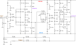
Here is a quick idea. It contains two operational amplifiers and two fully-fledged audio power amplifiers each, of which the right-hand part operates in true class B with very low quiescent current and the left-hand part would only be suitable for headphones - because this stage is the important class A output for high-impedance load conditions.
The result is now a 100W_peak class A amplifier, which, however, only has 10 watt losses in idle mode.
The trick here is the coupling bridge network; among other things, the left amplifier no longer sees an 8 Ohm load, but a much larger load (to put it very, very simply and casually). In reality, the whole process is not that easy to explain and it is certainly not trivial.
Here is the working approach. Have fun with it.
greetings,
HBt.
This Holy Grail includes a current supplier, an output stage with more or less transfer distortion and a control amplifier, also known as a voltage amplifier, which trumpets the A mode into the ether.
Through tricky, almost magical bridge wiring, the class A market crier also lifts the transfer/crossover-distorting power amplifier to Olympus. So they say, or would like to.
Both concepts do indeed work, often extremely well. But what is the advantage of such an undertaking? Actually none, because why should one design an amplifier that has faults - in order to correct them later, i.e. to work very hard internally. Yes, there was something, namely Douglas Self with his blameless approach. This approach says: just do everything right from the start!
What a nasty thing to do, because with Douglas Blameless-Amps, the field of amplification tools has been grazed.
Long story short, let's play.
Here is a quick idea. It contains two operational amplifiers and two fully-fledged audio power amplifiers each, of which the right-hand part operates in true class B with very low quiescent current and the left-hand part would only be suitable for headphones - because this stage is the important class A output for high-impedance load conditions.
The result is now a 100W_peak class A amplifier, which, however, only has 10 watt losses in idle mode.
The trick here is the coupling bridge network; among other things, the left amplifier no longer sees an 8 Ohm load, but a much larger load (to put it very, very simply and casually). In reality, the whole process is not that easy to explain and it is certainly not trivial.
Here is the working approach. Have fun with it.
greetings,
HBt.
Attachments
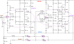
For all those who immediately recognize the schematic:
Yes, it is Matsushita (i.e. Technics & Panasonic) s “Class AA” seal.
Whether the DIY concept really works in practice remains to be seen, as we are still looking in vain for frequency compensation or any other stabilizing measures. But perhaps I can provide an interesting start for a project that will enter the race with advance praise.
HBt.

Unfortunately I don't have any internal Matsushita documentation on the Class AA concept, but it does exist. Apart from that, there have been countless advertising leaflets and brochures on the subject since the early 1980s. The service manual of the legendary SE-A100 comments on the concept on the first few pages.Do you have some documents regarding how class aa works?
This is absolutely correct, but I assume that an SR of >10[V/µSec] will already be sufficient for various test runs.My quick simulation suggests it requires a very fast/responsive "current" amp to make it work.
In any case - and, of course, it's also a really cool design, it looks really simple, doesn't it?It would be nice to play around with LTspice simulations.
Would serve also as a simulations training project.
😉
I just read 50 amperes per µSec! That is the specification for the SE-A100 according to the manufacturer, SM page 4.
But this power amplifier is also a real monster, with 480 W pk per channel into 4 ohms.
😱😎
But this power amplifier is also a real monster, with 480 W pk per channel into 4 ohms.
😱😎
The secret
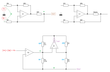
It's relatively simple if you know how to build a real power /current-source. It makes sense to consider the number with an ideal operational amplifier, for example according to “Howland”. This requires positive and negative feedback loops.
The secret is: the voltage amplifier N2 must regulate its Ud = Up - Un towards zero due to the principle of the vanishing input variable, and it will do anything until its output voltage gets stuck at one of the supply rails. It therefore constantly checks whether the actual output voltage also follows the voltage at the positive input - and this is the voltage at the complex load of our loudspeaker. In our case, N1 works as a classic differential current source par excellence, while N2 takes on the function of the voltage follower. This now means that if we consider the network (a classic bridge whose bridge voltage is automatically regulated towards zero) consisting of R1 to R4, then the current loudspeaker impedance directly determines the necessary current. It determines the level of the instantaneous constant current of the source N1.
This is a classic voltage-current converter, with one decisive difference: the entire control loop ensures that the load itself determines the current it needs for the required voltage drop (specified by our input voltage at N1).
The complex load therefore enters into a reciprocal relationship and thus becomes an active, determining part of the entire controller.
Everything understandable? Probably not. The main thing is: R1 * R2 = R3 * R4
Attachments
If N1 can supply the current required at this point in time in an infinitely short time, i.e. if the bridge voltage is already zero (i.e. everything is regulated, steady state), then N2 no longer has to supply any load current. This means (ideally) that the IP-VAS is completely free of any load and virtually sees the LS as an infinitely large resistor or impedance.
Quite an ingenious affair.
Bye,
HBt.
Quite an ingenious affair.
Bye,
HBt.
I think the real deal breaker is N2 has to be very low output impedance. Otherwise N2 could not override the distortion produced by N1. It makes impossible to use high performance low power opamp as N2.
my fault, sorry 🙄The main thing is: R1 * R2 = R3 * R4
R1 * R4 must be equal to R3 * R2
!!!
Technics (brand) also uses this principle in their preamplifiers, and it works perfectly with OP amps alone.I think the real deal breaker is N2 has to be very low output impedance. Otherwise N2 could not override the distortion provided by N1. It makes impossible to use just opamp as N2.
R1 = min. 3 times R2
and
R3 = min. 10 times R1
logical why this is so.
😉
Confirmed. Class AA is practically working with the configuration below. The current amp provides the most of the current.
The THD is much better than with the Current Amp alone.

The THD is much better than with the Current Amp alone.
I know that, which is why this concept has fascinated me since my 18th birthday, rewarded with ...! (as a gift).The THD is much better than with the Current Amp alone.
The residual THD is all from the class A amp (...)
You have thus successfully proven what the engineers and advertising experts of the Japanese parent company have been telling us since 1985 - class A without the losses of a conservative representative with Iq = sqrt(Pmax / Rload).
Cool.
Compared to the current dumper, which only has one ( and a botched one at that 😉 ) amplifier, Technics Class AA requires two, two fully-fledged amplifiers!
At first glance one can see that the term forward error correction is nothing more than a phrase for positive feedback (loop).
The AA system uses a voltage-controlled (inverted) differential current source (according to "Howland"). Reversed because the original inputs, positive and negative, carry the same potential - and now become the output node, while the actual (original) current output node is now modulated by the voltage-o.control amplifier.
The AA system uses a voltage-controlled (inverted) differential current source (according to "Howland"). Reversed because the original inputs, positive and negative, carry the same potential - and now become the output node, while the actual (original) current output node is now modulated by the voltage-o.control amplifier.
- Home
- Amplifiers
- Solid State
- AA50W - A conceptual idea