Agree
Technically superb
But squeaky sound
If it squeaks, then the amplifier is definitely broken
I know all three models listed here inside out, and they have never squeaked. Unfortunately, my super-cool VX800 fell victim to an explosion and my mother broke the V50 ... the rest is history.
In 2017 I restored a V50 and prepared/somewhat modified it for the 2020s -> THD flat and constant -112dB over the entire range.
It's clear that such a construction no longer has its own sound, but if it squeaks - then a drop of oil often helps, or just simply turn the ignition key of the Jaguar!

Heurica
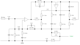
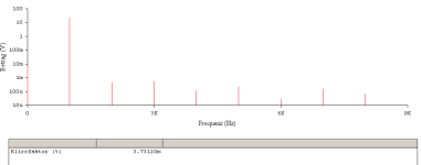
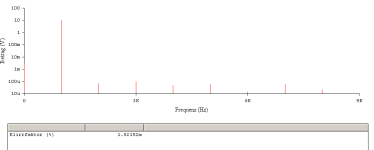
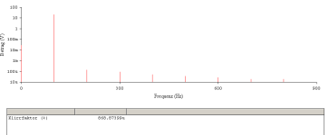
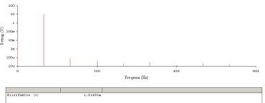
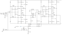
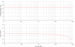
Here is the last (simple) example with the LF356 operational amplifier and its CFB-Afterburner as output stage (with +6.8dB voltage gain). The Class AA bridge network now follows the SVI4004 hybrid. The resulting bandwidth is huge, the GBWP is also remarkable. Stability problems do not seem to exist, the over-all compensation is very easy to implement with four small ceramic disk capacitors. CLG = 20dB, fu < 1Hz, fo > 200kHz, THD on average not greater than -73.6dB (entire range & full scale, the best number is -101dB).
Iq on average approx 50mAdc.
Attachments
-
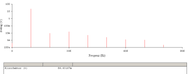 THD_10kHz_20Wrms.PNG10.2 KB · Views: 59
 -
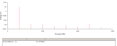 THD_10kHz_5Wrms.PNG10.1 KB · Views: 56
 -
 THD_1kHz_20Wrms.PNG10.2 KB · Views: 48
 -
 THD_1kHz_5Wrms.PNG10.1 KB · Views: 48
 -
 THD_100Hz_20Wrms.PNG10.3 KB · Views: 47
 -
 THD_100Hz_5Wrms.PNG9.7 KB · Views: 67
 -
 AA50W_final.PNG40.2 KB · Views: 77
 -
 perfekt_freq.PNG43.2 KB · Views: 69
Last edited:
Apparently I'm the only one fascinated by the concept.
😢
Compared to the discrete power operational amplifier, which is nothing more than a blameless amp that requires 2 x 14 BJTs, my combination only needs an extension of 2 x 4 BJTs.
The potential of this circuit (and its topology) is gigantic and it will be worth investing in research again. The THD already achieved with an LF356! alone, taking into account the enormous bandwidth of the system, suggests unimagined heights - and with relatively minimal effort.
The current dumpers cannot do this, even if they appear to be similar, the typical dumper topology is not really thought through to the end. This Japanese concept is!

HBt.
SU-VX800

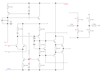
As a follow-up, probably the last network of the BJT's Class AA before the MOS-Fet number was introduced.
As a follow-up, probably the last network of the BJT's Class AA before the MOS-Fet number was introduced.
Does anyone have any questions about this somewhat more complex amplifier approach? This experiment, or rather this concept idea, is also absolutely recommendable in my eyes.
Please replicate it - and shower hbt.audio with praise in 2025 😎.
Happy new year,
HBt.
🚀
Please replicate it - and shower hbt.audio with praise in 2025 😎.
Happy new year,
HBt.
🚀
Very interesting, I'm working on something else at the moment. But I'm reading along. How about a prototype or is the circuit just an idea?
Hello moschfet,
there is no test circuit or even a prototype yet. But that's not a problem, the simulations clearly give a start signal. The concept itself is extraordinary - and an amplifier that works perfectly according to this concept approaches the absolutely neutral, i.e. the ideal. In my opinion, this approximation is the best, because the output signal must vectorially follow the input signal!
If a simple implementation with two ancient standard operational amplifiers and two times four transistors seems to guarantee the predicted success, then we should definitely test it.
Greetings from our state capital,
HBt.
- Home
- Amplifiers
- Solid State
- AA50W - A conceptual idea