I'm trying to put together an a75 and am truly baffled. To start with, is it just me or is the hookup for the fan printed wrong on the board? R18 is hooked up to drain of Q1 and should be from base/gate to ground. The led seems wrong too.
THE BIG PROBLEM
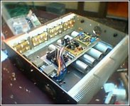
The big issue is that i'm getting alot of AC ripple on the regulated supply. aprox 250mV 😕 SEE THE PICTURES i ATTACHED
IT GETS WEIRDER
The chassis is set up in a way that places the psb and the input board as well as the rectifiers and fuses on a 3mm aluminum plate which sits on the transformer at one end, held down by the transformer bolt, and two 70mm stainless steel pins on the other side. The plate is very firmly grounded to the rest of the chassis with a nive, heavy gauge ground bus wire BUT THERE'S STILL A 250mV AC POTENTIAL FROM THE PLATE TO GROUND. AND THE 70MM PINS GET REALLY HOT
Do I need to keep the plate a good distence away from the transformer? I even grounded the transformer bolt with a wire to earth ground. Is this the same 1/4v I see in the regulated supply? Should I stick to buying SONY?
PLEASE HELP.
THE BIG PROBLEM
The big issue is that i'm getting alot of AC ripple on the regulated supply. aprox 250mV 😕 SEE THE PICTURES i ATTACHED
IT GETS WEIRDER
The chassis is set up in a way that places the psb and the input board as well as the rectifiers and fuses on a 3mm aluminum plate which sits on the transformer at one end, held down by the transformer bolt, and two 70mm stainless steel pins on the other side. The plate is very firmly grounded to the rest of the chassis with a nive, heavy gauge ground bus wire BUT THERE'S STILL A 250mV AC POTENTIAL FROM THE PLATE TO GROUND. AND THE 70MM PINS GET REALLY HOT
Do I need to keep the plate a good distence away from the transformer? I even grounded the transformer bolt with a wire to earth ground. Is this the same 1/4v I see in the regulated supply? Should I stick to buying SONY?
PLEASE HELP.
Attachments
You can't place an aluminum plate on top of the transformer and ground the plate. That gives you a shorted turn for the transformer. DO NOT RUN THIS SETUP, as it may blow.
Magura 🙂
Magura 🙂
Ditto - use insulated standoffs to prevent the shorted turn if the plate needs the support. the voltage you see on the plate is the result of the current flowing plate-leg-chassis-bolt. This current is probably coupling to your regulated supply, causing the ripple.
and yes, if you are using the Audioexpress boards, there is an error in the fan circuit. It will apply full rail voltage to your fan. Poof! (I ended up with 60 volts on a 12 volt fan that screamed for around 20 seconds) there is an unmarked hole in one of the traces around the fan regulator pass transistor that allows the proper connection to be made.
I assume that you found the silk screen errors on the main board.
I found the LED circuit correct.
EDIT: nice looking amp.
dinu,
In my case I have used 4 CRC's
5 * 5600 MicroF + 0.5 Ohms 30watts + 5 * 5600 MicroF
added some 100 micro F plus 0.1 micro F,
gives 2*40 Volts and the ripple is down to 80 milli volts...
To see the details picture #5
http://www.passdiy.com/gallery/a75-p11.htm
Regards.
PS: For the fan I have made a temperature regulated supply in 12 VDC
and didn't use the original pcb {with the pb}... it's DIY ; but don't hesitate
to ask!
Alain.
Wow, what a great community of helpful people! Thanks alot guys.
Now I can't wait to get home and rework.
As for the silkscreen errors, a few yanked out hairs later, I think I got them all. The article posted on the passdiy site seems to include the corrections. I just wish audioxpress made that clear with the instructions in the article they send with the boards.
The way the article shows the LED connected right to those tabs gets you + rail and - rail. (100v potential) anyway, I was thinking of just using a high value voltage divider to the unreg side so you can see the LED dim as the caps discharge on shut down. (OPINIONS?)
THANKS AGAIN 😀
Alain,
Just saw your post. I've been following your A75 and, like everyone else was very impressed. That tap problem got everyone pretty fired up. As for that 12v temp control. I'd love to see it. I was just thinking of just placing a thermal switch on the fan to kick on at about 65c.
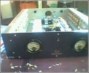
Here's another pic of the face plate. Like the meters?
By the way, what do you think of your amp sound wise.
Just saw your post. I've been following your A75 and, like everyone else was very impressed. That tap problem got everyone pretty fired up. As for that 12v temp control. I'd love to see it. I was just thinking of just placing a thermal switch on the fan to kick on at about 65c.
Here's another pic of the face plate. Like the meters?
By the way, what do you think of your amp sound wise.
Attachments
that would work fine - just pick a resistor that will drop the voltage at the 20 mA or so you'll need. Check the power in the resistor and use one rated for at least double the dissipation. You could also go rail to rail. Either way it will take a few minutes to dim out. If it stays lit a long time, you might want to put bleeder resistors across the PS output - maybe 5K 2W. The idea is to bleed it off fast enough that the charge will be gone before you can unscrew the case top and get to it.
the LED on the PSU board is in series with a couple of resistors that limit the current and put the LED pins at close to ground portential. If you measure across the terminals without an LED you will see 100V, but as soon as you put the LED into the circuit, the current flows and voltage drops. I ended up using 15K 1/2W resistors to keep my blue LED intensity reasonable. It's about a 30 second fade out here.
I like my A75s - they aren't as pretty as Alain's but the sure sound nice.
Hi Alain. I figured I'd see you here, too. 😉
Bob,
I didn't even hook up the led when I saw that 100V. What you're saying makes sense though. I'll try hooking it up as is. Worse case, I'm out a 50cent LED. I did place bleeder resistors on the caps. At 5k they do take awhile.
Thanks for the help, by the way.
I didn't even hook up the led when I saw that 100V. What you're saying makes sense though. I'll try hooking it up as is. Worse case, I'm out a 50cent LED. I did place bleeder resistors on the caps. At 5k they do take awhile.
Thanks for the help, by the way.
dinu,
the A75 is working with a pair of Electrostat Martin Logan Aerius i
and the preamp a CCS-X-Bosoz
I have listened to a lot of Class A amplifiers and others, especialy here in Montreal there is a "Festival du Son" each year ; to listen to the world best Hi-Fi set-up's
I am pretty happy with this, and enjoy every second of music! 🙂
To be honnest, the only one that impressed me last year was a pair of Passlabs XA250!!! I think they are not cheap, but sooooo good...
I am working on a Tube SE 6C33C-B 2*20watts and a pair of
back loaded horns with Fostexe's...
PS: BobEllis is a talented builder, but too modest! 🙂
🙂
For the temperature regulation I'll check my notes.
You have done a great job! 🙂
Alain.
the A75 is working with a pair of Electrostat Martin Logan Aerius i
and the preamp a CCS-X-Bosoz
I have listened to a lot of Class A amplifiers and others, especialy here in Montreal there is a "Festival du Son" each year ; to listen to the world best Hi-Fi set-up's
I am pretty happy with this, and enjoy every second of music! 🙂
To be honnest, the only one that impressed me last year was a pair of Passlabs XA250!!! I think they are not cheap, but sooooo good...
I am working on a Tube SE 6C33C-B 2*20watts and a pair of
back loaded horns with Fostexe's...
PS: BobEllis is a talented builder, but too modest!
🙂 For the temperature regulation I'll check my notes.
You have done a great job! 🙂
Alain.
dinu,
Welcome to the A75 Club !!!!!!! one of the best DIY designs !
Thanks to the Master.
Hey Bob, pleased to see you here! ; thats a lot of watts gathered here!
Pure Class A ; wouahhhh ! Bob is alway there to help and a real friend.
I can tell that 2 friends have listened the A75 and all were pleased
with the details, the stereo image is wide and in case of big orchestral
pieces it's a marvel! {Compared to Audio Research D100 and other's}
The only drawback in summer ; you must use the clim.
Enjoy!
Alain.
Dear All,
Start to make my A75 before, have few questions consult to your preempt.
1) I have 2 300W 2 x 40 VAC transformers not sure it can be applicable for using on output stage supply ?
2) Additionally, I have made one +/- 68VDC regulated supply, does it sutiable for input stage supply, so I can't adopt the voltage doubler design ?
3) In hand I have 14 pairs of Hitachi J56 & K176 MOSFET want to substitute IRF power stage . Thereby two technical problem in my mind , ONE) I only make an A75 with 14 pairs output each channel use 7 pairs, is it possible ? TWO) Don't know they can directly use in the circuit not need to do revise ?
Thanks for your instructions.
CK
Bob, I read your thread when building your a75. I'm not sure I understand what you are talking about with the coupling caps. And also, I saw nothing about an extra diode with the audioXpress package. Could you enlighten me?
ck - I modded my A75s to use a 42 -0- 42 C transformer I had. It works fine.
1 - That should give you ~54 volt rails. 300 VA is a little small, unless you reduce your bias to areound 1.5 A total given the higher voltage. It ought to get you going, be sure to provide adequate ventilation for the transformers
2. 68 volts is suitable for the 55 volts you can get with your output stage tranny- watch the dissipation on the 10K resistors from the cascode gate to ground. You can increase this value a bit to reduce dissipation or just use a 1W resistor in this spot.
the dissipation in the input differential will be high - over 1/2 watt. The IRFd210/9210 will take it, but with reduced life. I ended up bending legs and using IRF610/9610s in their place. They don't get quite so hot and sound a little better.
3. I think your hitachi devices are at least 150 watts. NP said that 6 pairs of IRFs should be plenty, so that is what I used. The catch for you is that the Hitachis turn on at lower voltages than the IRFs. You need to rework the Vgs multiplier to avoid driving your output stage full on. Turn it into a Vbe multiplier substituting something like a MJE15030 for the IRF610. You may also want to look for the Hafler DH-500 schematic (or another lateral mosfet amp) and copy that biasing scheme. The connections are the same in a Vgs multiplier, so you can just change the resistors and transistor.
Enjoy the A100 (depending on your heat sink capability you should be able to get 100 watts class A with 54 volt output rails, and at least 125 in AB.
Dinu,
I should have said DEcoupling caps - use around 100 uf from each rail connection to ground, right at the board power connection. Although my oscillation went away with a 2 uf film cap, I used 220 uf, 2 uf and 100nf on each rail to be sure.
By any chance, has any of you put in any kind of output protection on your A75? Or maybe you could make some suggestions. I have a nice pair of Joseph Audio speakers I'd like to keep as is.....just in case.
Although a bipolar Vbe multiplier can probably be made to work, I think you'll find that you get better bias stability if you use a MOSFET as a Vgs multiplier. The thermal characteristics will match those of the output devices more closely. A lateral device would be easier to adapt to this purpose than the IRF part (I think the A-75 uses an IRF510 or 610, but I'm quoting from memory and could be wrong).
Bob's suggestion about looking at the Hafler DH-200 or DH-500 bias circuit is a good one, but the parts might not be available these days. Wouldn't hurt to look for similar parts, though, if that should turn out to be the case.
Grey
Bob's suggestion about looking at the Hafler DH-200 or DH-500 bias circuit is a good one, but the parts might not be available these days. Wouldn't hurt to look for similar parts, though, if that should turn out to be the case.
Grey
Thanks to all your inputs :>
1) I have planned to use x2 300W transformer for it , does it get enough ?
2) Actucally, I don't know how to rework the bais part circuit. So do you know I need not make any change, just adjust the bais voltage around 1.7V - 2V for the PWD MOSFET operate ? Can this master circuit support I do that ?
CK
CK
one transformer per channel will be adequate if yo don't bias too highly - 1.5A total will around 160 W drawn, a little over half the transformer's rating (a DIY rule of thumb is never use a component at more than half its rated power) This would give you 36 watts Average into 8 ohms class A, 72 Peak - more than enough for most home use. You'll still have around 150 W average in class AB.
The bias circuit must change to use your hitachi outputs. A Vgs Multiplier multiplies the gate-source voltage of the IRF610 by a number greater than 1 depending on the ratio of pot setting and the fixed resistor above it (R60). Since Vgs on an IRF610 is on the order of 4 volts, you're going to have too much bias voltage for your outputs. That is why I suggested using an MJE15030 for Q11. Your reference voltage (Vbe) will be around .6 V so you can set up your multiplier to give you a reasonable bias voltage. You can probably use the circuit just changing Q11, but be sure to use a multi-turn trimpot for P3 or you will drive yourself nuts trying to set the bias.
I tried to attach the DH-500 schematic but it is too big. Email me if you want a copy.
Actually, all the pots should be multi-turn types. I wish I had spent the extra $3, it would have saved an awful lot of aggravation.
Grey -
The hafler DH500 uses a bipolar (NP2222A) in its bias circuit. I suppose it is relying on the negative temperature coeficient of the lateral devices. It does not use source resistors, either.
Dinu,
Nope, I did not add any protection to my A75. I might have, had I ended up with more room in the case. there are several threads here that deal with protecting against output faults. The DH500 schematic also has a protection circuit based on an op amp and a few general purpose transistors that does turn on delay and DC detection.
As for the extra diodes, I cannot remember the connection but I think than they were on Q9 and Q10. The purpose was prevent input stage damage if overdriven, IIRC. Perhaps AudioXpress will provide the update info to you - they should have included it.
thanks alot Bob. That helps. If you could email me the DH500 schematic it would help alot. I read alot of the threads and find the technical explanations a bit confusing sometimes. Are there any good books that can help with these apparently fundamental EE principles. Much to the amusement of some of you out there I'm an ME. Basic electrical design is all that was required and I was only too happy to fulfill the minimum at the time
- Status
- Not open for further replies.
- Home
- Amplifiers
- Pass Labs
- a75 power supply problems