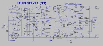
What I meant was at 15 Pf , the hellraiser has 5 Mhz bandwidth and can exceed 350V/uS slew.
This can be achieved with silver mica and low Cob semi's. Modern parts can exceed any adcom
or typical OEM by many factors.
OS
This can be achieved with silver mica and low Cob semi's. Modern parts can exceed any adcom
or typical OEM by many factors.
OS
Pass and Curl just do "trickle down economics". dribble down low fi Shat...
These designs are true SOTA AB. PPM is expected !!
Read the wolverine thread , they are "elite"... actually better than typical topping/benchmark
performance.
OS
These designs are true SOTA AB. PPM is expected !!
Read the wolverine thread , they are "elite"... actually better than typical topping/benchmark
performance.
OS
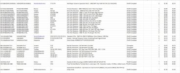
ok ostripper I'm now understanding that it's a highly performing product...I actually don't need a modular system: I would like to create a version of this power amplifier developed on a single PCB (stereo version) . So, confirm if I understood correctly please. The attached bom refers to the entire input stage: servo, vas, CF etc. , so at this stage there should be all the information I need to redo a diagram with kicad. The entire bom relating to the medium and high power stage would therefore be missing (from Q101, Q102 onwards so to speak). if everything is correct, where can I find it? Thanks again and sorry if I haven't understood correctly yet. un saluto Ros
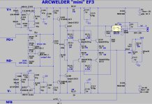
Here is the "standard" EF3. Slewmaster/Wolverine/my new stuff ...
There is at least several hundred of these working nice on the planet.
Including my old amp , the HK680.
2-3 output pairs use to-220 drivers. 4 + use to-3p sankens as driver pair.
Sanken 2sa1294 /2sc3263 are 35-40mhz with lowish Cob , better than some to-220 drivers.
Run 10 pairs , 1KW superamp.
For a sub amp , even 3-4 pair @ 50V rails can approach a KW.
OS
Attachments

well, thank ostripper, it seems we are starting to get there; I hope to start schematic in kicad soon.
Now I'm also looking for the BOM of this final stage and the documentation of the cn1 output.
Can I bother you again if I have any doubts? for the moment thanks ostripper, a good day to you and all the other guys.
Now I'm also looking for the BOM of this final stage and the documentation of the cn1 output.
Can I bother you again if I have any doubts? for the moment thanks ostripper, a good day to you and all the other guys.
Hi, I am just wondering, do both the A60 and the A60+ variant's offer the Class A and switching AB setup or is that only for the A60+?
Hello everyone,
After reading this thread, I got inspired to build an A60++ power amplifier. I have already ordered almost all the components for the project, and they should arrive soon. My plan includes using a single 500W transformer, two amplifier boards, and a case styled after the Accuphase E550.
In my audio system, I currently use the Eversolo A6 Master Edition and slightly modified Quadral Aurum Vulkan VIII speakers. I would like to control the entire system with a single remote or smartphone. Therefore, I am considering implementing the module from the link below into the power amplifier. Thanks to the "trigger in" function of this module, I could power on the amplifier with a delay after turning on the Eversolo.
https://matway-electronics.pl/pl/p/Standby-6w1-SOFT-START-DC-Blocker-PSU-GLB-kontrola-fazy/200
Do you think this is a good solution?
I look forward to your thoughts!
Dear Forum Members,
I received A60+ amplifier boards from a seller on AliExpress. The attached photo shows what I received. The board is completely different from the description and the photos provided in the seller's listing.
It lacks visible high-current traces, Omron relays, and even soldered connectors for transformer power input.
Do you think requesting a refund for these boards is justified?
Attachments
![20250109_190515[1].jpg](/community/data/attachments/1313/1313295-9df723c46d2dc0aa99ab8ee95e1574d1.jpg?hash=viAj5qlxwq)
IMHO Need to looked at the lot on Ali. They often write and translate in such a way that it is easy not to understand what you are buying in the end.
https://pl.aliexpress.com/item/4000...t_main.58.21ef1c24gK0Aab&gatewayAdapt=glo2pol
Before I ordered the amplifier boards, I thoroughly examined the offer from every angle. The photos and description make it perfectly clear what you are buying.
Before I ordered the amplifier boards, I thoroughly examined the offer from every angle. The photos and description make it perfectly clear what you are buying.
I think there's nothing to worry about. On your board is printed V1.2, In the ad they show boards V1.0 and V1.1. I would be happy to receive the newest version.
Here are som samples of what I found on Taobao and AliE:


Good luck!
🙂 morten
Here are som samples of what I found on Taobao and AliE:
Good luck!
🙂 morten
You are absolutely right. After a thorough analysis of the components on the PCB, I have to say that the parts are of quite good quality. Indeed, there is a newer version of the A60 board. I was expecting a board marked A++ 1.1, but instead, I received A+ 1.2. The number of plus symbols was misleading. It's time to get started with the assembly. First, I’ll measure the components on the board and pair the power transistors. Thanks for calming me down—sometimes we react too emotionally instead of taking a closer look at the problem first.I think there's nothing to worry about. On your board is printed V1.2, In the ad they show boards V1.0 and V1.1. I would be happy to receive the newest version.
@Berlusconi Hope it's going well on your side. Starting with my amp again, allot of other toys/hobbies that side tracked me. 🤣 Quick question, I got 2 toroidal, each boards getting the own, the toroidal got 2 pairs of 13vac outputs with the 38-0-38vac outputs. I did a measure on the 13vac outputs and getting 14.5vac. My question is, can I use the 14.5vac 0.77a to switch on the speaker protection on the board? will it handle the 14.5vac, or must I get 12vac transformers?Thanks @Berlusconi . I will take a photo over the weekend when i get the heatsink. The fins alone is 10cm long on the heatsink. It was cut off a massive piece of heatsink so i think it's going to look really nice and work really nice. i just need to send it in for machine work to prep the mount area for the board.
Here is some info on the toroidal:
Other DIYers can jump in if they got info.
Thanks.
The circuit contains a 7812 regulator, it works with an input voltage of up to 35 volts. The capacitors in its circuit, the Chinese have 25 volts, which is also enough. But it is better to check.Other DIYers can jump in if they got info.
Thanks @Topa41 👍 Lets check what other say to. If that can work, then it will use that outputs of the toroidal.The circuit contains a 7812 regulator, it works with an input voltage of up to 35 volts. The capacitors in its circuit, the Chinese have 25 volts, which is also enough. But it is better to check.
Myślę, że nie ma się czym martwić. Na twojej płytce jest wydrukowane V1.2, w reklamie pokazują płytki V1.0 i V1.1. Byłbym szczęśliwy, gdybym otrzymał najnowszą wersję.
Oto kilka przykładów tego, co znalazłem na Taobao i AliE:
View attachment 1405443
View attachment 1405444
View attachment 1405445
View attachment 1405446
View attachment 1405447
Powodzenia!
🙂 Morten
Unfortunately, I ended up in the hospital, so the implementation of the A60+ project has been delayed. Thanks again for getting in touch.
However, I still have some questions regarding how to connect the amplifier PCB. On the photos you attached, there are clear terminals for connecting the audio input to the amplifier PCB, but on my boards, someone (an idiot) made a three-pin connector—I'm not sure why. Similarly, I'm uncertain about the audio input and power supply connections. The soldered connectors seem intended for power supply connections, given the "AC" label next to them. The audio output connectors appear to be the screw-type terminals. Previous forum posts described things differently, hence my confusion. Additionally, the lower PCB was covered by the Chinese genius with some coating, making the labels that are clearly visible on your PCBs completely unreadable on mine.
I also have another dilemma, given that I'm a novice in electronics. I'm confused about how to connect the separate power supply board (with capacitors) to the amplifier PCB, especially since the amplifier board already seems to have a built-in power supply section.
Thanks again in advance for your help!
Attachments
![20250311_121735[1].jpg](/community/data/attachments/1341/1341656-7d410973570c38459040dacddda89b3f.jpg?hash=8stHIpQhUM)
![20250311_121743[1].jpg](/community/data/attachments/1341/1341657-59491b76ebcb3224075ccb66c66a995e.jpg?hash=MufcDPlo4z)
![20250311_133358[1].jpg](/community/data/attachments/1341/1341658-d2972efdfe2b33f6807d15eef6f213fe.jpg?hash=Kioviy2XcZ)
Last edited:
I removed the green terminals and installed the knives. The inscriptions AC-0-AC are the power supply of the amplifier itself from the transformer, example 36-0-36v. The inscription AC-0 is the 12v power supply to the protection circuit from constant voltage and the connection delay. The green block is the amplifier output to the speakers.
- Home
- Amplifiers
- Solid State
- A60(+) Amplifier. Build this?