
D
Deleted member 543346
I think most of the ppl doing diy do appreciate the feeling of building something on their own...either from sctratch or more completed modules.
For me it is about the road to completed product , where i can choose layout , chassis , components and sutch.
Have you ever seen a diy'er taking on a new project after successfully built something he or she has been overly happy with? Yes i have 😀
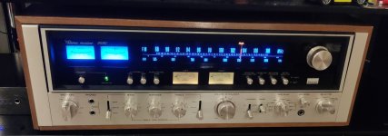
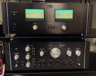
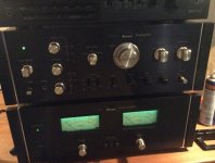
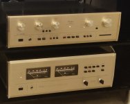
Having my accuphase setup along with Sansui BA power and pre , Nakamishi PA 7E II plus other goodies does not stop me to be searching for new projects and repairs.
Maby i like the A60+ or maby not , but then i allways have the option to use chassi and components on wolverine later on.
For me it is about the road to completed product , where i can choose layout , chassis , components and sutch.
Have you ever seen a diy'er taking on a new project after successfully built something he or she has been overly happy with? Yes i have 😀
Having my accuphase setup along with Sansui BA power and pre , Nakamishi PA 7E II plus other goodies does not stop me to be searching for new projects and repairs.
Maby i like the A60+ or maby not , but then i allways have the option to use chassi and components on wolverine later on.
Attachments

Hi all, been a while since I was on this forum. I recently purchased the A60 boards with the three pairs of the 2SC5200 and 2SA1943 output transistors. My question is what do I set the bias at, the instructions are extremely vague and difficult to understand. When setting bias,do you put a duumy load on the output? There is also no mention of the DC offset level which I assume is as low as possible. There is no way to adjust the DC offset. I am using 2 x 300watt toroidals, one for each channel.
The instruction sort of says 50millivolts for the bias level. Any help would be greatly appreciated.
Happy Easter to all.
The instruction sort of says 50millivolts for the bias level. Any help would be greatly appreciated.
Happy Easter to all.
Attachments
I would advise you to read all the information, there are 38 pages in total. Since other questions will appear and have already been discussed here more than once. In short, there are 2 microcircuits on the board, one 1237 to protect the speakers from constant voltage at the output with a delay in connecting the acoustics. The second a square 8-pin microcircuit is just for adjusting the zero offset at the output. With your small radiators in the test location, set no higher than 20mV at a temperature of 40 degrees, otherwise overheating and failure.
I am working on an eight pair version right now. Nearly done actually. There is no offset adjustment because the amplifier design includes a DC servo circuit to maintain a close to 0 offset. This is the OP 7 op amp and associated circuitry. Bias level in mv. is what everybody talks about but what is important is the total bias current which will be a dependant of the mv. across the emitter resistors and the resistor value. Some versions of the amp have different values for the emitter resistors. In my case I am using .27 ohms. If I set the bias to 27 mv then the current will be .027v/.27ohms = .1amps -100ma x 8 transistors = 800ma total. Then you need to look at the total power being dissipated in the output stage by multiplying your total bias current by the total power supply voltage. If I have +-50 volt supplies then the total power would be .8 amps x 100volts = 80w/channel. So your heatsink would need to be able to dissipate that much power and still be at a reasonable temperature- (45-50c maximum.) I would start with a bias level of 25mv which seems to be the minimum that folks on this thread have used. After you determine that everything is stable and working properly then you can attempt to increase bias current if you feel it’s needed. For setting bias you do not need a load on the output but you do need to short the input so that no noise or RF is picked up and amplified, which would make adjusting the Dc bias difficult. Good luck and happy listening!Hi all, been a while since I was on this forum. I recently purchased the A60 boards with the three pairs of the 2SC5200 and 2SA1943 output transistors. My question is what do I set the bias at, the instructions are extremely vague and difficult to understand. When setting bias,do you put a duumy load on the output? There is also no mention of the DC offset level which I assume is as low as possible. There is no way to adjust the DC offset. I am using 2 x 300watt toroidals, one for each channel.
The instruction sort of says 50millivolts for the bias level. Any help would be greatly appreciated.
Happy Easter to all.
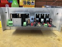
Carefully Wolfgang! Your "heat sinks" aren't adequate. Aluminium shet isn't enough to transfer such heat.50millivolts for the bias level
@Bfpca, @Paroxod4 and @Erlend Sæterdal provided you with excellent guidance, just get some adequate heat sinks.
I recommended reading the forum and looking at all the photos that the guys posted here. There is no point in repeating everything that has already been stated, confusion is possible. There are questions about possibly different boards and configuration values, you can ask a question here. About setting up this amplifier, excuse me, there is already 150% information Berlusconi chewed everything out very well.

Hi to all, apologies, bad photo doesn't show the full extent of the heatsink. The dimensions are 310 x 120 x 50mm with fins. It came from an inverter.
Got it all connected up today and tested it, one side worked fine the other side, a 4.7 ohm resistor burnt out. Don't know why. It is situated right next to the two 10,000 uf caps and the test point. I will post a photo. Will do as everyone has suggested and read the whole thread. shortcuts are never good. Thanks to all.
Got it all connected up today and tested it, one side worked fine the other side, a 4.7 ohm resistor burnt out. Don't know why. It is situated right next to the two 10,000 uf caps and the test point. I will post a photo. Will do as everyone has suggested and read the whole thread. shortcuts are never good. Thanks to all.
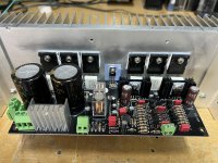
Those heatsinks should be able to dissipate some power but you still need to be careful and adjust bias using the heatsink temperature as your guide rather than some arbitrary mv recommendation. Do you know where the 4.7 ohm resistor is on the schematic?
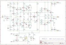
OK, If connected as per the schematic that 4.7 ohm resistor can only get hot if there is a large HF AC signal across it. This would indicate the amplifier is oscillating. Check the soldering of the resistor and make sure it is not shorted to either supply rail. If the wiring checks out and the 100nf capacitor is also OK then you probably have an oscillation. Not a nice problem to have! I would check all the components to make sure they are the correct values and also check the soldering for shorts and bad connections. Did you solder the components on the boards yourself or buy them preassembled? When building my own A60 amplifier modules I built the circuitry up to the output stage and then I tested it for proper operation before adding the output stage. This allowed me to have confidence that there would be no surprises when the high current section of the amplifier was added. I can write up the procedure I used and post it if anyone is interested.
Some basic testing of the A60 today. Assembly is nearly finished and I was able to set the DC operating point and monitor noise and DC offset at the outputs. All seemed OK so I connected a signal generator and checked gain which was 27 or 28.6db. I connected 4 ohm 40w resistors to the output and checked distortion at 1khz with a Kiethley 2015 meter. The meter has a noise floor of about .004% and at 2w out into 4 ohms the distortion was in the noise floor of the meter at .004- .006%. At an output of 8V- 16w into 4 ohms it measured .022%. At 13.5v-45w output it measured .033% This is a crude measurement system but the amp seems to be functioning normally. Both channels had pretty much identical measurements . With the input shorted the wide band AC noise at the output measures around 100uv. Next will be to look at bandwidth and get a more complete picture of the power output capabilities. I ended up with 47-48 volt power rails so I expect around 100w at 8 ohms. I have a single 800VA toroid and an off board rectifier and initial filter caps of 24kuf / rail followed by .15 ohm resistors in series to the amp board capacitors giving a CRC supply filter. PS noise measures 32mv AC on the rails which is a good number.
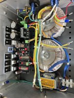
Hi to All, good news replaced the dodgy 4.7 ohm resistor and she is now operating. I tested the DC offset and as suggested by someone, it was non existent / very low, 1 millivolt. I set the bias to 20millivolts per channel and the temperature of the heatsinks was 41 degrees Celsius which seems pretty good. Ok, this is going to be a silly question, I noticed that the ground on the amplifier is common between the input, output and 0 voltage point on the AC in point. my question is, do I still have to run a common ground for both channels. The ground is not connected to the chassis ground. I have made up one of those ground loop breaker units but have not connected it yet. Worth doing or not? When nothing is connected except the speakers, it is nice and quiet but when you connect something up to it, you get a hum. If you plug two RCA's into the inputs, still quiet. If you plug the other ends into a preamp for example, hum appears. I am open to any suggestions on this. Thank you so far, you have all been extremely helpful. Just for information, I am using two 300va toroidal and a small 12 volt tranny for the speaker protection. The chassis is all aluminium home brew.
Good news Wolfgang! I have installed a ground breaker on my A60+. I have not reached the point of connecting the amp to a source component other than my signal generator. Noise was low in that configuration but I may need to make some changes in a full system connection. You should try connecting the 2 channel input grounds together at the RCA connectors. Also I have in the past connected that point directly to chassis ground. You could also try connecting it to the far side of the ground breaker. There are lots of theories on grounding out there and lots of different plans. I believe there is even a grounding method discussed earlier in this thread. Often it is very difficult to physically implement many of these schemes after you are finished construction. For that reason I have experimented as mentioned earlier in this post and have been able to find a method that works in most cases.
Two 300VA toroidal transformers guarantee very low noise, if connected properly as two monobocks. Two channels will touch each other in just one point, at the RCA grounds. 12 V transformers for speaker protection must have two separate 12VAC coils, otherwise it will cause ground loop if you share a single secondary coil.I am using two 300va toroidal and a small 12 volt tranny for the speaker protection. The chassis is all aluminium home brew.
There is my problem, I have one only secondary on the 12 volt transformer. It's funny, that is where I thought the problem could come from. I will change it to a dual winding tranny.
- Home
- Amplifiers
- Solid State
- A60(+) Amplifier. Build this?