simply
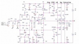
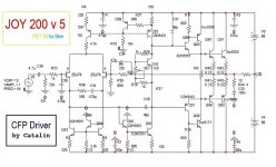
Joy 200 v4 .Testing ...
Slew rate 150V/uS ,Thd(Pout>20W,1khz-20khz,5 harm) =0.0003%
here have been improvements: the thermal regime, phase reserve, THD, slew
rate, TID, the driver failure, etc.
Outputs is still enjoying the benefits of sziklai .
🙂
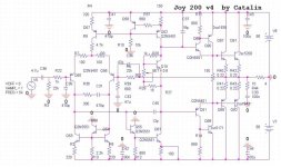
Joy 200 v4 .Testing ...
Slew rate 150V/uS ,Thd(Pout>20W,1khz-20khz,5 harm) =0.0003%
here have been improvements: the thermal regime, phase reserve, THD, slew
rate, TID, the driver failure, etc.
Outputs is still enjoying the benefits of sziklai .
🙂
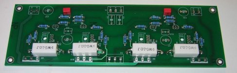
Attachments
Catalin you are a genius
can put a pair of FETs on input?
do you sell PCB on EBay?
🙂 😎 🙂
see this
http://www.amb.org/audio/beta22/
can put a pair of FETs on input?
do you sell PCB on EBay?
🙂 😎 🙂
see this
http://www.amb.org/audio/beta22/
Attachments
thanks catalin
for still working with the wonderfull sziklai and also its very welcome and nice to see updates and improovements
thank you
for still working with the wonderfull sziklai and also its very welcome and nice to see updates and improovements
thank you


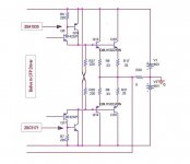
Stee last year I was 2 times in Milan. 🙂 I still don't belive that is better to get rid with 47uF capacitor.The error voltage (in output ) will be splited by 22k/680 so in dc the V offset will be bigger(volts).
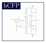
PMA you are a GURU
can we know more about your CFP amp?
Catalin
in my amp I always delete DC offset CAP
drift maximum 0.4V
sound much better 😉
when you are here can listen 😎
can we know more about your CFP amp?
Catalin
in my amp I always delete DC offset CAP
drift maximum 0.4V
sound much better 😉
when you are here can listen 😎
catalin said:Stee last year I was 2 times in Milan. 🙂 I still don't belive that is better to get rid with 47uF capacitor.The error voltage (in output ) will be splited by 22k/680 so in dc the V offset will be bigger(volts).
The error voltage(dc offset) will compare the output voltage by a factor of 22k/680 since in output we don't have an voltage divider.Pls show your schematic
Re: CFP Driver
stee ......
it seems to me that you are a person that really working with electronics ..... i understand that this consume a quiet big if not the bigest portion of your every day .....
i wonder though how come its possible one person to flood arround so many threads with so many schematics ..... when one schematic is a variation of the other and so on and on and on ....
then again i wonder how a person can have such a strong relation with a simulator .....
wouldnt it be better if you just focus in one schematic and then construct it and work on it for the possible variations and improovments ?????
i dont mean to be rude or apply critisism for someone i dont know but i was just curious ......
i actually enjoy people that study electronics and dont work with fast food solutions .....
many happy regards sakis
Stee said:continues to be a possible solution
for a high-contrast sound 🙄
stee ......
it seems to me that you are a person that really working with electronics ..... i understand that this consume a quiet big if not the bigest portion of your every day .....
i wonder though how come its possible one person to flood arround so many threads with so many schematics ..... when one schematic is a variation of the other and so on and on and on ....
then again i wonder how a person can have such a strong relation with a simulator .....
wouldnt it be better if you just focus in one schematic and then construct it and work on it for the possible variations and improovments ?????
i dont mean to be rude or apply critisism for someone i dont know but i was just curious ......
i actually enjoy people that study electronics and dont work with fast food solutions .....
many happy regards sakis
another thing
what i wanted to say also is that so far i constructed repaired and updated almost a gozilion amplifiers and i still dont have a simulator ....
but on the other hand i never designed my own amplifier since my theory is quiet poor for a thing like that ....
many happy regards sakis ( with sexy avatar he he he )
Re: CFP Driver
When are you going to stop?
yet more nonsense posted by Stee.Stee said:continues to be a possible solution
for a high-contrast sound 🙄
When are you going to stop?
Andrew, maybe not quite on this one, I like to experiment myself with some never used ideas but obviously the theory must work.
The scheme by stee here is used by some fine very expensive highend manufacturers, let me rather say that scheme without it being a cfp. It has its advantages and disadvantages, now with a cfp it might be interesting. I use the cfp ef too but with some simple mods to further improve it, especially when it comes to crossover artifacts. The scheme by stee can also be further refined.
This might be one of stee s better ideas, Ill see what can be had of this.
Plenty current can be flowed, if I can give you one reference look at eletrocompaniet outputstages, theres something they do very well, loads and loads of powerful clean bass. I have 2 nemo s and 2 aw250 amps, for bass I havent heard any amp of any price be better at low frequencies.
I can supply a schem if you want to have a look.
I can supply a schem if you want to have a look.
>18W through each 220r and hitting >65W on peaks. You are joking that any competent amplifier is closely based on Stee's schematic.
Yes not with the values he has, do you have email, Ill send a proper schem. The resister is best exhanged for a current source, stee must get his basic electronic theory right.
Yes, that's why I wish he would stop posting his "perfect" schematics.homemodder said:The resister is best exhanged for a current source, stee must get his basic electronic theory right.
Rather, he should be asking how to make them work.
There are dozens of them now and they are littering threads around this Forum.
- Status
- Not open for further replies.
- Home
- Amplifiers
- Solid State
- a wonderfull sziklai