You mean, a 17mA increase. ?If we set for example a 20 mA for 35 degrees Celsius on the heatsink and then heating the powerstage to raise heatsink temp at 50 degrees the current is going to 17mA which is pretty good .This is measured at my amp.
I had found, quite the same, from simulations.
"If we set for example a 20 mA for 35 degrees Celsius on the heatsink and then heating the powerstage to raise heatsink temp at 50 degrees the current is going to 17mA which is pretty good .This is measured at my amp.
"
This means that is decreasing not increasing .Please read carrefuly
"
This means that is decreasing not increasing .Please read carrefuly
A decrease of the quiescent current for a temperature increase at the output transistors is surprising to me.
Sorry, I must be missing something.
Which are the thermal couplings in your amplifier ?
Sorry, I must be missing something.
Which are the thermal couplings in your amplifier ?
My couplings,on the heat-sink are only 2sc5200+2sa1943 and the Vbe multiplier .
Only these .2sc5171 2sa1930 are disposed on another isolated heat-sink .
therefore the current is decreasing if the temperature is raising and it increasing if the T of heatsink is decreasing 🙂 .
this also happens when all final +pre-final transistor +Vbe multiplier are on the same heat-sink .But more faster .
Hi everyone,
I have this stuff with "2 pair of SanKen" on output stage
this is so popular kits here in my country
but so many "lies" there
kit that I have
"BLAZER HIGH POWER AMPLIFIER 500Watt - SC 3858 / SA 1494"
I didn't know if this 500watt just a joke, before I join diyAudio
now I want to know how to maximize this 500Watt amplifier kit
how much it will be max voltage, min speakers impedance, etc?
& what modification should be take?
how to make it real 500Watt @4ohm?
some info
the VBE multiplier (use KSE340 on the kit) is on main heatsink with output tranie & those driver (C2073 & A940) has it own heatsink (2 pieces heatsink)
I have try similar stereo kit with 45volt DC supply but the sound is not to good
just wondering how to make it smoother sounding
Any input well be welcome,
note I'm just a beginner, please suggest me simplest modification that can be made
Thanks
Sorry if I post in a wrong place.
Current sharing OP's
I was not talking about temperature issues but i was refering to the current sharing of the output transistors. If you use BJT's from the same production batch, they match probably close enough. I would personally opt for emitter degeneration.
Nice design, have fun!
best regards,
Piersma
As I said there is no reason to fear this topology.the amp is going very well even at high temperatures for about 4-5 years in this topology.
The transistor are not well matched but this is not an issue.
I was not talking about temperature issues but i was refering to the current sharing of the output transistors. If you use BJT's from the same production batch, they match probably close enough. I would personally opt for emitter degeneration.
Nice design, have fun!
best regards,
Piersma
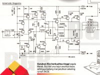
schematic similar as that from ebay
At the real kit, Tr C2344 replaced with C2073, A968 replaced with A940 & resistor on its collector 2 x 100R not 2 x 120R.
VR 4k7 & the wiper goes to base MJE340(VBE) drawing mistake on schematic I guess
From +- 70volt supply this will be wrong specification
This was I had in my mind, 70volt / 8 ohm = 8.75A Then the power P = (612.5 watt) – (some losses) = 500watt (make sense) 😀 how pity me
I was believe in this spec…😀,
wonder if it spec can be realize...
Regards
This is the schematic, similar as post #160 on ebayHello ,I can't help you because I don't know the schematic which you have .
At the real kit, Tr C2344 replaced with C2073, A968 replaced with A940 & resistor on its collector 2 x 100R not 2 x 120R.
VR 4k7 & the wiper goes to base MJE340(VBE) drawing mistake on schematic I guess
From +- 70volt supply this will be wrong specification
This was I had in my mind, 70volt / 8 ohm = 8.75A Then the power P = (612.5 watt) – (some losses) = 500watt (make sense) 😀 how pity me
I was believe in this spec…😀,
wonder if it spec can be realize...
Regards
Attachments

...... and PCB for this nice sounding amplifier right here 🙂
Alex .
Thank you alexmm for the pcb design. Can you post the pcb layout for etching? Thanks in adavance.
Regards,
Boyet
500 watt from 2 pairs of output transistors, 700 watt in 4 ohms ?? I hope the designer has more common sense than that and or is a good liar and looking to make a quick few bucks.
I am agree ,it a lie that this can handle 500w/4ohms.It can reach to 500 w but for short term because the output transistor can't handle such power.
You can mod it by putting in paralel 4 transistor (2npn + 2pnp )on each channel
You can mod it by putting in paralel 4 transistor (2npn + 2pnp )on each channel
Thank you alexmm for the pcb design. Can you post the pcb layout for etching? Thanks in adavance.
Regards,
Boyet
..... you will find in attachment PCB in pdf. 🙂
Regards Alex.
Attachments
Homemodder's concerns are confirmed by the first page specification.
500W into 8r0 and 700W into 4r0 indicate that the output voltage has started to collapse trying to drive a 4r0 resistor. (-1.55dBV ref. 8r0)
This tells me and should alert everyone else reading, that the amplifier is not capable of driving a 4r0 load.
That leads to the conclusion that the amplifier is not capable of driving an 8ohms speaker.
Would it drive a 16ohms speaker? The output power is likely to be ~280W into 16r0.
Using that bit of implied Power we can then go forward and determine a suitable output stage.
For FETs use 4times 280W of output devices. A 2pair output stage using 250W devices is probably close enough to work well.
For BJTs use 5 to 6times 280W of output devices, i.e. about 1400W to 1700W of output devices.
This results in a 4pair of 200W devices run on that +-90Vdc for 280W into 16ohms speakers.
I cannot see how any designer can claim 1000W unless he only expects car audio as his audience.
Last edited:
I'm a little confuse about it, putting in pararel "more" 4 transistors?I am agree ,it a lie that this can handle 500w/4ohms.It can reach to 500 w but for short term because the output transistor can't handle such power.
You can mod it by putting in paralel 4 transistor (2npn + 2pnp )on each channel
this kit already have 4 transistors per channel.
Maybe you mean add another 4 transistors, total 8 transistors per channel to get
500 w @ 4 ohm & supply +-70VDC, right? just to make sure...
Then after I do add 2 pair transistors or maybe 3 pair for more safety?
this will be 500 w + 500 w stereo amp.
That picture was from stereo kit that why write 1000 watt, who write is a liar 😀
so many lies here 😀 where I live 😛.
Thanks to you all to tell me the truth
Anyway I'm not go for 500w @ 4 ohm yet,
maybe better for me to try this 2 pairs @ lower voltage
for only 2 pair I guess +-56 volt is maximum.
& better is someone can tell me
any way to make this amp sounds more "soft"
where is the key?
I want to try mod some resistor maybe 470R/5w (post #163 & #164)
but don't know if that safe or not to do.
or better just leave it,
this amp just can't be help this just old design not so good.
Regards
You will get ~+-57Vdc from a 40+40Vac transformer.
or
~+-50Vdc from a 35+35Vac transformer.
Both of these will be far more likely to suit that design than 50Vac or 60Vac transformers.
or
~+-50Vdc from a 35+35Vac transformer.
Both of these will be far more likely to suit that design than 50Vac or 60Vac transformers.
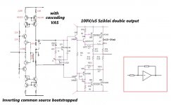
Sakis is this design another that you have found to be good sounding and so asking for it to be simmed. Im just curious as I find the compensation used interesting, miller is accross beta enhancer and then lag compensation is used on the vas.
- Status
- Not open for further replies.
- Home
- Amplifiers
- Solid State
- a wonderfull sziklai