Member
Joined 2002
Russ White said:Jason, The controller we supply is very similar to the kookaburra. It uses a volume pot which is ready by an ADC on a microntroller which does the actual switching. The pot is not in the signal path. So it works exactly like an ordinary volume pot or rotary stepped attenuator.
Cheers!
Russ
I already know that.! What i'm asking is , s this device a faster one or slower one. can the relays keep up with the turning of the knob ?
jleaman said:
I already know that.! What i'm asking is , s this device a faster one or slower one. can the relays keep up with the turning of the knob ?
Well, it works pretty much as fast as you can turn the knob. 😉 There is no rotary encoder which your post mentioned. Thats why I explained how it works.
Member
Joined 2002
Russ White said:
Well, it works pretty much as fast as you can turn the knob. 😉 There is no rotary encoder which your post mentioned. Thats why I explained how it works.
SWEET! thank's Russ. The one i have nos is annoying and slow Sounds good but when you need to turn down the stereo because of a phone or something it takes to long its faster to press pause on the cd-player..
Is your relay based volume pot workable with 12V
jleaman said:Is your relay based volume pot workable with 12V
Only if you change the relays from 5V to 12V and design a new controller. The current controller is designed for 5V and has its own PS on the controller.
4" x 1.5" Allow for about 4.5" x 1.75" or so for PCB + connectors dependant on how you decide to wire it. A stuffed relay PCB is about .625" tall without standoffs. The conttroller is about 1.125" tall without standoffs.
Cheers!
Russ
Cheers!
Russ
Russ White said:4" x 1.5" Allow for about 4.5" x 1.75" or so for PCB + connectors dependant on how you decide to wire it. A stuffed relay PCB is about .625" tall without standoffs. The conttroller is about 1.125" tall without standoffs.
Cheers!
Russ
Are both relay PCB and controller boards have the same size?
Thanks
Member
Joined 2002
jleaman said:I dont want to build another transformer into my pre-amp i could use a 5V regulator tho 🙂
It already has a regulator. And trafo from 5 - 12V should work.
jajabin said:
Are both relay PCB and controller boards have the same size?
Thanks
Yes width and length wise they are both 4" x 1.5" 🙂 Sorry I did not make that clear. My mistake.
Member
Joined 2002
The reason i ask is because my power on relay switch has a 12V output i canuse to power my relay volume pot so i can reduce the amount of transformers in my chassis 🙂
J'
J'
Single side layout for G6H
Ok Craig, and a few others.
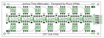
I have completed a layout for the Joshua Tree with G6H relays instead of G6K. The G6H relays are larger so the board is a bit larger at 5.6" x 2".But it is full featured.
Its actually a much better layout than he first one I posted.
What do you guys think?
Ok Craig, and a few others.
I have completed a layout for the Joshua Tree with G6H relays instead of G6K. The G6H relays are larger so the board is a bit larger at 5.6" x 2".But it is full featured.
Its actually a much better layout than he first one I posted.
What do you guys think?
Attachments
Member
Joined 2002
Re: Single side layout for G6H
Super Now i shal order one and a input Selector. 🙂
Russ White said:Ok Craig, and a few others.
I have completed a layout for the Joshua Tree with G6H relays instead of G6K. The G6H relays are larger so the board is a bit larger at 5.6" x 2".But it is full featured.
Its actually a much better layout than he first one I posted.
What do you guys think?
Super Now i shal order one and a input Selector. 🙂
The single side G6H version I just posted above will be for those who want to etch their own PCBs. I will will post PDFs as soon as I have verified the layout by building one myself.
Also please note that due to single side routing considerations the pin out of the controller interface is different from interface port (IDC) on the controller posted before. So I will be designing a new "DIY" self etch single side controller to go with this relay PCB.
The board looks good. I now have a use for those 25 relays. Do you have to do a new controller or could we make a different cable using KK molex pins on one end instead of IDC?
Craig
Craig
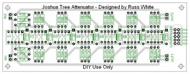
Hi Craig, the older controller is not made for 10pin IDC but 14pin. I have redone the sinle side PCB once again this AM. Now the PCB will accept the ordinary Joshua Tree controller. I will work on a single side version of that controller as well.
Cheers!
Russ
Cheers!
Russ
Attachments
Now I am confused. The pictures of the controller on your site show 10 pin IDC, not 14. Are they old pictures?
I meant the single side controller I had released a couple months ago. The one on the site is 10pin and will work with the PCB I just posted. 🙂
OK. I have no problem buying the controller board and PIC from Twisted Pear and building a hybrid set up. Have you looked at the new layout to see if it is possible to locate mounting holes so that your current controller will stack on it?
You are doing such fabulous work, I hate to ask for more details. I owe you a few brews if you are ever in the Valley. Should hit 100 this week, so beer time is definitely upon us.
Craig
You are doing such fabulous work, I hate to ask for more details. I owe you a few brews if you are ever in the Valley. Should hit 100 this week, so beer time is definitely upon us.
Craig
- Status
- Not open for further replies.
- Home
- Design & Build
- Parts
- A twisted tale about a logarithmic relay attenuator