Thanks Craig. 🙂 Any season is beer season for me. I don't think I can add holes where they would need to be, but I will make a controller that is the same size as the G6H PCB.
Cheers!
Russ
Cheers!
Russ
No problem. If I am digging out the stuff to make boards again, may as well make three as two. I just thought some holes would fit between the resistors on each side. It is time to upgrade to this board as I am tiring of my 4 pole dual control cermet 25K pot. The Bosoz deserves better.
Craig,
Good news for you on two fronts.
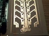
1) Looks like I saved you some etchng/drilling as I have a board finished for you. If you feel like beta testing it then it is yours.
2) The controller board can be made to sit on top no problem. Just place the controller PCB over the relay PCB and mark the spots for the holes.
There will be a controller PCB and a programmed PIC in the package as well. 🙂
The traces are tight but it actually etched very well. I tested the relay power traces for continuity and shorts and they are absolutely fine.
Contact me by email with your address if you want it.
Cheers!
Russ
Good news for you on two fronts.
1) Looks like I saved you some etchng/drilling as I have a board finished for you. If you feel like beta testing it then it is yours.
2) The controller board can be made to sit on top no problem. Just place the controller PCB over the relay PCB and mark the spots for the holes.
There will be a controller PCB and a programmed PIC in the package as well. 🙂
The traces are tight but it actually etched very well. I tested the relay power traces for continuity and shorts and they are absolutely fine.
Contact me by email with your address if you want it.
Cheers!
Russ
Attachments
the JT with 2 relayboards is for balanced stereo, however if i wanted mono balanced would i have enough with 1 relay board?
I'm not sure that's why I'm asking ...
if so, is it then also possible to control multiple JT's with your "multi kook and perch" you designed for the kookaburra?
I'm not sure that's why I'm asking ...
if so, is it then also possible to control multiple JT's with your "multi kook and perch" you designed for the kookaburra?
bramht said:the JT with 2 relayboards is for balanced stereo, however if i wanted mono balanced would i have enough with 1 relay board?
I'm not sure that's why I'm asking ...
if so, is it then also possible to control multiple JT's with your "multi kook and perch" you designed for the kookaburra?
yes on both counts. 🙂
BrianDonegan said:So, it seems I left 3 parts out of the first batch of JTs I shipped. The controller parts bag is missing the shrouded pin header and IDC connector. Also, the 5K pot. I am sending these parts out today.
When did you send this stuff out? I didn't get them in my kit and haven't seen anything from y'all yet. Already picked up a pot thinking I needed to supply one, but hadn't found the pin header or connector and was going to dig through some old computer stuff to try to find something I could cannibalize. 🙂
C
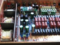
Relay Chatter with Joshua Tree
The relays in my Balanced Joshua Tree Configuration will chatter and/or run continuously during volume changes when it is installed in my preamp. It is connected to a Balanced Darwin configuration which it powers and receives its power from an 8VAC 1.5A transformer.
Interestingly enough I do not have any problems when the Joshua Tree is tested outside of the preamp. All four sections track very consistently and provide over .8V output from a 1V signal generator input.
The problem I am having with the installed Joshua Tree continues even when it is totally disconnected (power and signal) from the Darwin and/or running off an external varistat and with standard power to the preamp disconnected.
The problem disappears when the JT is pulled from the Preamp and operated externally.
Anyone have any ideas what could cause this?
Attachments
Wow, I am not sure what the problem is, but the first thing I would suspect if Power/GND interaction of some sort.
Maybe try electrically isolating the JT from the preamp case. I am still mulling this over. If you can't seem to get it to work I can reprogram the PIC with firmware that should correct the problem if you send it to me.
Cheers!
Russ
Maybe try electrically isolating the JT from the preamp case. I am still mulling this over. If you can't seem to get it to work I can reprogram the PIC with firmware that should correct the problem if you send it to me.
Cheers!
Russ
Thanks for your reply Russ.
One of the first things I checked was the the ground to shield connectivity.
The case is 1/4" Oak covered by 3/4OZ Copper Flashing from Home Depot and I thought that the flashing might be interacting with the signal ground. While the shield connectivity went up through the standoffs I could not find any connectivity from the standoffs to signal ground on any of the three boards.
Roy
rpafenberg said:
One of the first things I checked was the the ground to shield connectivity.
Hi roy. One thing you might try is putting a 2.2-4.7uf cap in place of the 100nf cap at C2 on the JT controller. That should help smooth out any transients or a flaky pot.
:EDIT: use a small electrolytic or tant. and orient the negative side toward the edge of the PCB.
Cheers!
Russ
Roy,
I just tried a 10uf cap at C2 with an old 10K pot that used to give me fits. Now it is nice and stable. Hopefuly changing to a larger cap there does that same you. It certainly can't hurt.
Cheers!
Russ
I just tried a 10uf cap at C2 with an old 10K pot that used to give me fits. Now it is nice and stable. Hopefuly changing to a larger cap there does that same you. It certainly can't hurt.
Cheers!
Russ
One of mine works fine but for one pop in the middle.
The other pops all along and also starts out at 2/3 volume or so and won't go below that - it will, however, go to full volume.
I've done a visual inspection (my magnifying glasses installed - got some good tools for that from the metal shop) and do not see any solder problems, though I could hav missed one of course. I was focusing on other issues and did not persue it further at the time.
C
Hi C,
The one that is working fine sounds pretty normal. If you have a little DC in the signal you can sometimes get a bit of a pop when some relays open/close. I am not sure what can be done about that except to eliminate the offset.
Your badly behaving relay is another problem. I would suspect a resistor in the wrong spot, or possibly a relay that is always on. Turn the volume to zero and check voltage at the relays power pins. They should all be zero. Also a short between resistors could be the problem.
Also double check your resistor values and make sure they are the same on both channels.
Let me know if you need more help.
Cheers!
Russ
C,
One other idea. Is it possible one of the relay PCB is connect to the IDC cable (relay power) backwards?
One other idea. Is it possible one of the relay PCB is connect to the IDC cable (relay power) backwards?
I doubt the one is connected backwards as it works properly for the last 1/3. Easy enough to double check, so I'll do that.
I suspected shorts between components from soldering and inspected for that, didn't see anything. I'll give it a more serious look-over again though (already planned)
Which are the power pins? That will definitely be helpful to check.
Resistors were installed on both boards at the same time, taking care to make sure they're identical. I generally did two or three at a time per board before soldering them up. I'll double check that too, though. I never got to a resistor and said "hey, that spot is filled" so I'm fairly confident this is done right.
C
The relay power pins are the two that the diode on each relay runs across. Also, while you are checking things, make sure the leads of the diode itself do not contact any pins other than the power pins which is acceptable.
Russ,
Tried a 10uF 25V FC for C2. While the JT appears to work properly during a fairly brief audio test I was still getting constant relay chatter once the POT was moved to pass audio.
Roy
Tried a 10uF 25V FC for C2. While the JT appears to work properly during a fairly brief audio test I was still getting constant relay chatter once the POT was moved to pass audio.
Roy
rpafenberg said:the JT appears to work properly during a fairly brief audio test I was still getting constant relay chatter once the POT was moved to pass audio.
I am not sure I follow you... can you please explain?
The pot should not be passing any audio.
- Status
- Not open for further replies.
- Home
- Design & Build
- Parts
- A twisted tale about a logarithmic relay attenuator