China doesn’t need to subsidize it’s postal services. The Universal Postal Union (UPU), which is a United Nations agency, has decided, in its infinite wisdom, that China is a poor underdeveloped country and thus entitled to large discounts on its postal rates. The postal services in the West foot the bill to the tune of hundreds of millions of dollars. Strange that Donald Trump hasn’t cottoned on to this yet.
Universal Postal Union = International Postal Union.
Boli46's statement seems to be a simplified and distorted view of the "Terminal Dues" (standard rates paid by each originating postal authority to terminating postal authorities) issue, which has been partly addressed by the IPU/UPU. Trump is aware of it, but doesn't understand it (as usual). See Trump administration seeks to end lower shipping rates for China and others.
The big picture problem the USA has is the same as Australia has. We don't make anything anymore - nearly everything consumers buy comes from China, regardless of whether they buy it via a local bricks and mortar store, or via the internet (ebay or whatever) direct from China. This means, that for the first time in history, consumer goods imports far outweigh consumer goods exports, and postal authorities terminal dues income from China does not sustain the costs of distributing Chinese postage.
As far as whole country economies such as Australia are concerned, there is no problem, its' balanced, because we export minerals and farm produce to China. But these exports go via ships at sea without involving the postal authorities. Thus what the Western postal authorities are losing thru low terminal dues, the governments are gaining in taxation of mining companies and farmers. Or should be, if their politicians have any brains.
Of course, if politicians (in USA and Australia) had any real brains, they would have addressed the reasons why we don't make anything any more.... (rise of the generic business manager class, over the top occ health & safety rules, competition rules preventing pooled R&D costs, etc etc)
Last edited:
I spent 41 years at Motorola in Plantation Florida. Our plants probably funded a similar sized factory at HP somewhere. There were several production lines and about 1000 engineers in its heydey.....At least 80% of the test equipment was HP.
I am currently recreating the RF workbench that I had at Motorola in 2014 by buying old HP stuff cheap and fixing it. I have good bit of it done, including a lot of stuff that cost big bucks in the 80's. HP 8664 generators, I have 4 working. 1 each working HP 8753C, Agilent 4352B, Agilent E4406A.......
Forum member rsavas worked in the Motorola Toronto facility.
Couple of the guys I was dealing with in the 1980s were moved to Florida, don't recall the names offhand now 30 yrs later. I think some may have gone to Schaumberg (Chicago) as well.
Mot gradually shrank to a sales & service location here. By the time I called it a day in 2010 (time to retire at 78) they occupied only one floor in the new bldg. They bought a couple of Aeroflex/IFR Wichita 3920s for servicing from the rep company I wuz working for. We also had some very nice Boonton & Noisecomm stuff for ripping apart digital modulation.
Didn't have to own much TE for a very long time, I had access to plenty state of the art, 24/7.
With a bit of luck I'll nail 87 this coming Friday.😀
Mot gradually shrank to a sales & service location here. By the time I called it a day in 2010 (time to retire at 78) they occupied only one floor in the new bldg.
That's much the same story as too many Western firms who were once big names, well respected.
At one stage (1970's) I worked for Philips. Philips were huge worldwide, and huge even in Australia - multiple large factories, employing thousands. Philips Australia now is just a minor distribution firm importing everything from China.
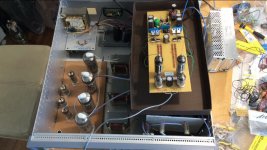
Amazing, stacked gain stages.😱 A lot of cct that with a little real design would be an order of magnitude simpler. The PT looks like a real misery.🙂
The PT looks like a real misery.
With some creative tube swapping to arrive at the right voltage demands, there might be a Tektronix scope power transformer that could be made to work. Yes, there are no coupling caps, but those 160 uF power supply caps are still in the signal path, as are all the vacuum diodes used for cathode bias. Maybe a box full of LED's would be more sonically benign?
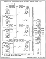
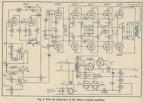
I found this diagram in an old copy of Audio Engineering (4/1951) Less the preamp, the main amplifier is fully DC coupled. No DC can be tolerated on the input, so C10 & C12 are mandatory. R39 & R40 provide DC stability through NFB as well as close matching of most parts. R24 & R38 will need readjustment as the tubes age. A full (low distortion) 15 watts is obtained with 0.35 RMS volts input.
Edit: This is the unedited version that Lampie519 posted in #225
Edit: This is the unedited version that Lampie519 posted in #225
Attachments
Last edited:
With some creative tube swapping to arrive at the right voltage demands, there might be a Tektronix scope power transformer that could be made to work. Yes, there are no coupling caps, but those 160 uF power supply caps are still in the signal path, as are all the vacuum diodes used for cathode bias. Maybe a box full of LED's would be more sonically benign?
Maybe not. Putting a power vacuum tube diode, such as the TV damper 6CG3, in series with an amplifier cathode is an interesting trick.
The grid of a triode (or tetrode or pentode) progressively looses control with signal increasingly negative - this is partly due to the three-halves-power rule of basic tube operation, and partly due to electrons finding their way around the grid instead of through it.
But with a diode in series with the cathode, with only a few volts across it, just as the amplifier tube cathode current is driven low by the signal, the diode increases its resistance, promoting the reduction in current. With only a few volts across it, a vacuum diode's anode resistance is somewhat inversely proportional to the current.
So, if you pick your tubes and operating conditions right, you can get a reduction in distortion beyond what a simple unbypassed resistor would achieve. A bit like ultralinear operation, where the curvature of the screen characteristic opposes the curvature of the control grid characteristic. Its a totally different effect to the cathode voltage regulating effect of LEDs.
Last edited:
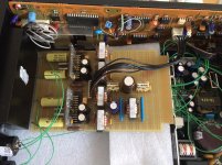
Keit, that is very interesting! I too have a good experience using diodes at the cathodes. Never did serious measurements but the quality of the sound increased in many cases, and that is what counts for me...
Attachments

Lampie519: I haven't done any serious measurements or analysis on this either. It's on my list of things to do. A list that contains a great many things to do.
My list is getting longer as i would like to try so many interesting circuits or improve over an existing one. I now am busy with a new D/A converter and a new Zotl amp (more power then the ones i have build in the past). Then i want to build a new HV amp for my ESL's (using some Zotl circuitry). i also am tuning my old Hammond organ... so you see, i have some things to do during this coming winter.
Attachments
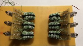

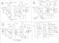
Direct vs Capacitor vs IT
A simple sound comparison between Capacitor, DC and IT coupling using a basic 2 stage balance PP amplifier. A/B switched between each and compared. Repeated this several times and ensuring the output gain was equal for all test. Not a comprehensive list of components but a list of items that I currently possess. No Feedback applied to the circuits.
I have allocated $ 0.00 for direct coupling cost, you will need to include extra costs for the power supply i.e. additional elevated heaters, and higher HT voltage.
There was not a significant difference in ‘sound’ between different capacitors compared to the difference between Direct and IT coupling.
Listening Impressions and schematics attached, these are my own personnel listening opinions.
Frank
Attachments
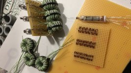
Coupling capacitors can be replaced by coupling transformers. Reservoir capacitors can be replaced by batteries (in case of DC power). Filter capacitors can be replaced by voltage/current stabilizers.
But what is the problem with capacitors?
But what is the problem with capacitors?
Yes of course coupling can be replaced by coupling transformers …I was looking for sonic differences.
From my limited auditions capacitors did not sound as nice as the alternatives. I was quite surprised by the results. From the cheapest (Orange Drop) to the most exotic (Teflon) they possess similar sonics even though the Teflon capacitor were the best of the capacitor bunch. The IT coupling was a huge step forward, the sound was clean and crisp.
Frank
Different coupling requires dramatically different bias arrangements and that will make more difference than the coupling component, although transformers have magnetic core distortion and self resonance that you may like.
Member
Joined 2009
Paid Member
bias
Direct coupling requires the driver plate voltage be the grid voltage of the output so you need a huge negative supply for the drivers or some other voltage stack arrangement. One reason direct coupling is not popular in tubes is because tubes age so you would have to constantly readjust the output bias.
Transformer coupling means the driver plate voltage is essentially the supply voltage vs RC coupling requires a significant drop across plate resistors. This means a transformer driver operates from ~half the supply voltage of an RC coupled driver.
Some sort of cathode resistance is essential for predictability in any case, and is minimized in the output where that would waste output power.
One direct coupling arrangement that works well is to wire the outputs as cathode followers but that requires a high driver voltage swing. The low impedance of cathode followers provides much better bass than a typical plate connected output transformer, as well as improved control of the transformer self resonance at high frequencies. However tube amps rarely afford the number of tubes required to do anything except the usual output topology.
I once corrected a tube driver circuit in a Bogen amp that achieved a clean 100Watts instead of the original 60W by changing some resistor values. The original driver circuit was just damn sloppy, as were many tube amps. Many tube amps were build by "rule of thumb" rather than being engineered, and if it worked at all people were happy.
Last edited:
Your circuit design with the IT has a CCS in the tail of the first stage, that's not much of a fair comparison.There was not a significant difference in ‘sound’ between different capacitors compared to the difference between Direct and IT coupling.
Listening Impressions and schematics attached, these are my own personnel listening opinions.
Frank
- Home
- Amplifiers
- Tubes / Valves
- A Tube amp without coupling capacitors? Possible?