Interesting topic.
Start on is a problem. With the 20-20, the 12ax7 is heater starved, therefore is slower to get online, while the EL84 are ready to conduct.
The result is for a few seconds the EL84s are unbiased and conduct like beasts.
This explained OT primary failure with this amp.
I added a B+ delay to let the tubes warm up and this worked nicely: no pop sound as the PP design cancels out the spike, and no current spike that I could witness in the primary.
I'll read the article but I thought diode are used in reverse to protect grid to cathode voltage. I usually avoid diodes in tube circuitry for noise issue.
Thank you.
Yes, noise is an issue when the diodes conduct, but here they don’t unless the voltage becomes positive. The diodes have a small capacitance and therefore i put 2 in series ( half the capacity) and still enough protection.

Nice one. Fixed bias on top. Cool. What power did you get out on this one?
There are a lot of DC SE designs, but DC PP design is rare.
There are a lot of DC SE designs, but DC PP design is rare.
PhilippS's amp uses a lot of parts, given the sound quality is likely no better than the standard triode-pentode audio output of a cheap radiogram or TV sound system, and may be worse.
A standard pentode output stage driven from the control grid is relatively immune to HT ripple. Driving the screen grid from a cathode follower has 3 disadvantages: a) higher distortion (screen grids are not a linear as control grids); and b) significantly more sensitivity to ripple, and c) lower gain, reducing the benefit of negative feedback (which reduces hum as well as distortion).
So, a lot more HT filtering is necessary.
Here's a good rule of thumb: If the old guys of industry didn't do something, there's probably a good idea why they didn't.
Last edited:
Keit,
One thing to consider from back then: cost.
We do things now for fun, and we can experiment design as we please.
The old guys had profitability in mind from the bean counter guy, so no room for crazy and costly ideas.
Now we can easily have a perfect B+ and even B- and many bias supplies.
I never came across a PP DC design with the driver stages driven from a B- supply to directly drive big power tubes.
Is this a crazy idea ?
Brice:
"One thing to consider from back then: cost.
There is no getting away from that fact that cost matters in industry, but its far far more nuanced than what you imply.
Some radios were built at the absolute minimum cost. That typically meant a pentode output with no neg feedback. But there was a very large market for something with better quality.
The next step up was a triode-pentode audio with a low amount of neg feedback. That meant a much flatter frequency response, and lot less distortion, for the extra cost of a triode (after the mid 1950's, the triode was in the same glass as the pentode) and three resistors and a capacitor.
The next step over the triode-pentode audio was push-pull with 2 triode pentodes. The extra cost of the extra triode-pentode was offset by being able to use a much smaller output transformer for a given power output and frequency response.
Nobody would have used the screen-driving circuit, because it would cost MORE than a push-pull circuit and give less quality than the SE triode-pentode circuit.
Beyond this point, things get more complex. For instance, in the USA, the use of the ultra-linear configuration was retarded due to a patent on the transformer. In Australia, the hobby magazine "Radio TV & Hobbies" (later known as "Electronics Australia") stumbled on a way to break the patent - after that, UL was taken up by industry here and in other countries and was very common, giving a modest further improvement in quality for an extra cost measured in cents.
Beyond this point, the extra money is best spent on larger tubes and on the output transformer.
Beyond that, the cheapest way to get better quality was usually the Williamson configuration (balanced triode driver between phase splitter and output tubes)
In other words, while cost is always important, there is a tree in the path to better sound. Going up the tree usually means better sound, but some branches are cheaper than others - and there's a few rotten branches.
""We do things now for fun, and we can experiment design as we please.
The old guys had profitability in mind from the bean counter guy, so no room for crazy and costly ideas.""
Certainly! But being silly isn't fun. Some of us ride bicycles for fun - not as fast or comfortable as a car, but it's fun. At the same time, we don't bolt lots of extra weight on the bike for no good reason.
"Now we can easily have a perfect B+ and even B- and many bias supplies."
But you don't need it, and it does cost your wallet.
Last edited:
PhillipS, i like this amp, but some adjustments and improvements can be made:
First here the diodes are mandatory on the grid of the Cathode follower. and secondly the pentode cathode follower should be a pentode cathode follower and not a triode strapped pentode. Just give it a try.
First here the diodes are mandatory on the grid of the Cathode follower. and secondly the pentode cathode follower should be a pentode cathode follower and not a triode strapped pentode. Just give it a try.
Nice one. Fixed bias on top. Cool. What power did you get out on this one?
I get about 8 W per channel, distortion is mainly 2nd harmonic.
I use this amplifier a lot and it performs quite well.
The output transformers have been developed especially for the 509/519 tube family in screen drive mode.
PhillipS, i like this amp, but some adjustments and improvements can be made:
First here the diodes are mandatory on the grid of the Cathode follower. and secondly the pentode cathode follower should be a pentode cathode follower and not a triode strapped pentode. Just give it a try.
Thanks, I will try this. The original reason fo rthe triode cathode follower was to get a low impedance driver needed for provideing screen current.
As mentioned before this circuit is based on the Synola amplifier. IIRC the motivation for development 20 years ago was the possiblity to use cheap (back then) sweep tubes that can behave quite linear in screen drive, instead of ordinary audio tubes like 300B. Of course the driver effort is higher so the benefit is questionable.
Best regards
Philipp
Building Something Different.........For Fun or Whatever
We do things now for fun, and we can experiment design as we please. The old guys had profitability in mind from the bean counter guy, so no room for crazy and costly ideas.
In all the years I've built audio amps I've-
1) never built a Williamson
2) never built a Mullard 5-10 or 5-20
3) never built s Dyna All that has been done by many others several times over.🙂
So built several amps that were at times quite different, driven by curiosity. One of the primary objectives was to keep cost under control.
Tube amps were never my day job, the day job was always hitech.
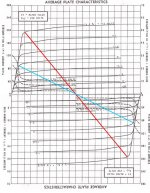
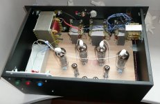
So here is one such amp, PP 6V6s DC driven by a CF 6BQ7. 26W on a regulated 340V DC PS 17W as built on self contained minimum PS +ve & -ve power supplies. The loadline is adjusted for AB2 operation, should anyone ask
Differential Cascode Front End, 6BQ7 into 4BQ7 (heater runs on 5V wdg) Common Mode Rejection >70 db. Built Spring 2004 Some may have seen this already, its been on DIY before.
At which point I got another 5 yr contract to go away & do what I do.😀
We do things now for fun, and we can experiment design as we please. The old guys had profitability in mind from the bean counter guy, so no room for crazy and costly ideas.
In all the years I've built audio amps I've-
1) never built a Williamson
2) never built a Mullard 5-10 or 5-20
3) never built s Dyna All that has been done by many others several times over.🙂
So built several amps that were at times quite different, driven by curiosity. One of the primary objectives was to keep cost under control.
Tube amps were never my day job, the day job was always hitech.
So here is one such amp, PP 6V6s DC driven by a CF 6BQ7. 26W on a regulated 340V DC PS 17W as built on self contained minimum PS +ve & -ve power supplies. The loadline is adjusted for AB2 operation, should anyone ask
Differential Cascode Front End, 6BQ7 into 4BQ7 (heater runs on 5V wdg) Common Mode Rejection >70 db. Built Spring 2004 Some may have seen this already, its been on DIY before.
At which point I got another 5 yr contract to go away & do what I do.😀
Attachments
-
 6V6GTA 14W 4 PushPull C 7W.jpg84.1 KB · Views: 100
 -
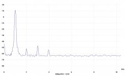 2013_03_02_001 One Watt.jpg40 KB · Views: 270
 -
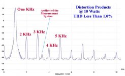 Distortion Products at 10 Watts B.jpg42.3 KB · Views: 290
 -
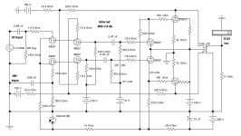 Cascode Amp H.PNG95.7 KB · Views: 302
 -
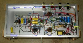 IMG_1383 Cascode Amp Bottom A 14W E Flash Labelled.jpg539.3 KB · Views: 274
 -
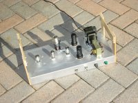 026 Cascode Amp A.JPG898.7 KB · Views: 280
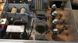
This is similar to the HV amp i have build for my Acoustats (input and driver stage). Instead of a transformer i use current sources (SRPP). In any case it is not 100% DC coupled as it still has 1 coupling capacitor in the signal.
Attachments
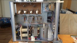
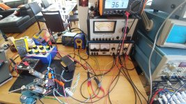
You have some nice TE, what is the blue screen box on top of your scope?
Good TE is something many try to do without. Finding our way in the dark is difficult to impossible,🙂
Good TE is something many try to do without. Finding our way in the dark is difficult to impossible,🙂
what is the blue screen box on top of your scope?
The Tektronix box on the bottom right in the picture is not a scope. It is a mainframe from their modular test system, possibly a TM503. There are plenty of different modules to fit into it including what looks like an audio oscillator on the left. There were several flavors of power supplies, and even a small scope plug in.
The blue screen object on top of that is a Tektronix scope, missing its name tag above the screen. I have a similar looking TEK 2232 except it has a row of buttons across the lower face of the bezel around the screen.
On top of that, is the pulse generator.
Tube amps were never my day job, the day job was always hitech.
Ditto....I spent 41 years in a Motorola plant, the last 28 were "defining the state of the art in radio communication." Before that I was a tech in the cal lab for 10 years, during the time that the TM series was new stuff.
Since retiring I have been outfitting my lab with 80's vintage TE, mostly HP stuff, one Ebay, hamfest, or equipment auction find at a time.
I'm similar to Tubelab in that I have equipped my own lab with a range of old and relatively new instruments. Some of my gear I have owned for 60 years - still good.
It has proved interesting buying old gear on eBay. Several items made by HP arrived in near perfect condition - only required old stores/accounting stickers cleaned off, and calibration. HP front panels were all painted. So, even if damaged, no big deal - they can be repainted and re-lettered.
Old Tektronix instruments from the tube era have engraved anodized front panels. If these panels are scratched or dented, they are a write-off, unless I can master the art of making new aluminium panels with compound curves. Unlike old HP gear, old Tektronix always arrives pretty much inoperative, but after lubricating switches etc, replacing tired tubes, and any carbon resistors gone high, is usually good for another 20-30 years.
A lot of old lab gear has a coating inside (if tube based) and outside of cigarette smoke condensation. Looks dreadful, smells, but cleans off easily with Electrolube Safewash or dishwashing liquid, toothbrushes and cotton buds, and a bit of patience.
Why does HP gear usually arrive in good order, and Tektronix not so? Better quality at HP? Or maybe the more expensive HP was originally purchased by major companies that looked after their gear?
One brand I steer clear of is anything made by Marconi. Marconi gear was good in its day. But old Marconi gear typically has a lot of faults, unobtainable parts made in the factory using techniques that can't be duplicated at home, and worst of all, usually has a lot of corrosion and rust.
Old Japanese professional gear holds up very well. YEW and Sanwa Multimeters I purchased 60 years ago are still in perfect condition. Quite unlike old AVO multimeters, which when new cost 10 times as much.
Last edited:
LabVIEW test automation
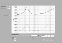
I'm a LabVIEW programmer, doing LabVIEW test automation for much of my career. I have a Agilent signal generator which is GPIB controllable and a Fluke 123 portable scope that can be interfaced (serial...Ugh). I can also get waveforms from a sound card or - of course - other NI interfaces which are a lot more expensive. I use the LabVIEW student edition which at $50 is a bargain - for me.
A colleague said "Do an impedance frequency sweep of your speaker in your cabinet" so I recently wrote a program to do so. Not that any other analyser program / programmer couldnt trivially do the same, it's just that I can make it operate however I want - as long as I can figure out the math - (It used to have phase information, but now I only have one channel as input, so I cant get the reference waveform input to do phase)
Attachments
Last edited:
here's one from 1948
New Direct-Coupled Amplifier p 12, 43, 44
pp 6l6
https://www.americanradiohistory.co...o-Craft-1948-Electronics-Reference-Manual.pdf
New Direct-Coupled Amplifier p 12, 43, 44
pp 6l6
https://www.americanradiohistory.co...o-Craft-1948-Electronics-Reference-Manual.pdf
- Home
- Amplifiers
- Tubes / Valves
- A Tube amp without coupling capacitors? Possible?