I would like to. What should I diy build?
Ucd Xlite - Kartino Surodipo
But I want warning you, you need to make PCB by yourself
- beware Fake components
- bad PCB design and you get trouble
- LPF Filter need carefully build
problem start to buy and get all required parts like Capacitor, parts for LPF Filter, switching Transistors.
Impossibile to get local
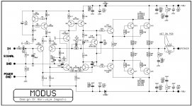
At Andrew's request, analysis of the Modus schema model.
because in the model there are no elements indicated in the diagram, close analogues were used.
features of the original scheme:
because in the model there are no elements indicated in the diagram, close analogues were used.
features of the original scheme:
- Q10 is not enough to stabilize the output transistors, that is, there is no compensation
- in the Bias trimmer, the slider "hangs in the air" if the contact disappears, the temperature circuit will be uncontrollable.
- For the correct operation of the capacitor C3, it is necessary that R7 =R8 + R9, however, this condition is not met. Total resistance R7 + R8 + R9 = 40 k ohm, therefore this circuit can be made up of two resistors with a nominal value of 20 kΩ each.
- in the supply voltage of the preliminary stages, diodes D1 D2 must be damped by a resistor, otherwise the charge of the capacitors will be with large peaks in the supply.
Attachments


Last edited:
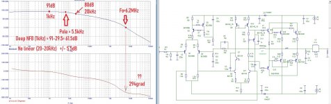
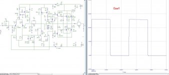
offered his own solution for the progressive correction of this amplifier. In fact, it already turns out a completely different amplifier in terms of characteristics and sound as well ...
highlighted his decisions on progressive correction in red. Also in this scheme, the multiplier has been improved and its work is sufficient for thermal stabilization of the output transistors.
Additionally optimized frequency gain circuits and added anti-clip circuitry.
The output transistors operate in class AB, so their bases must be powered from a single resistor, and the bases of complementary transistors themselves must be connected with a capacitor so that it is possible to discharge parasitic capacitance in power transistors to facilitate switching these power transistors.
If something is not clear about the attached files, ask questions.
Attachments
Last edited:
H,offered his own solution for the progressive correction of this amplifier. In fact, it already turns out a completely different amplifier in terms of characteristics and sound as well ...
highlighted his decisions on progressive correction in red. Also in this scheme, the multiplier has been improved and its work is sufficient for thermal stabilization of the output transistors.
Additionally optimized frequency gain circuits and added anti-clip circuitry.
The output transistors operate in class AB, so their bases must be powered from a single resistor, and the bases of complementary transistors themselves must be connected with a capacitor so that it is possible to discharge parasitic capacitance in power transistors to facilitate switching these power transistors.
If something is not clear about the attached files, ask questions.
The 220pf attached to the base of Q12 to ground, should this be also moved and attached to the base of Q9 and not on the ground..?🤔 I think the 4.7pf attached to the base of Q8 and collector of Q7 can be omitted. In my actual build using this type of VAS the miller cap in the left leg does not have much effect in the amps stability. (with or without) but the cap in the right leg works effectively.
Thanks for sharing your mod!
Regards,
Albert
Last edited:
H,
The 220pf attached to the base of Q12 to ground, should this be also moved and attached to the base of Q9 and not on the ground..?
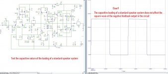
in no case should you do this, Douglas Self made a mistake in suggesting such a correction option, the reason is that if you put this capacitance in the base of Q9, then your actual capacitance in the load of this transistor will be equal to the capacitance of the capacitor multiplied by the gain of this transistor, which makes it almost impossible to control the output stage current.
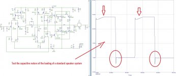
This capacitance is needed by the output power stage to limit the spectrum at the input, because the output stage operates with 100% negative feedback and its unity gain frequency is higher than the upper frequency of the real load (speaker system)
I think the 4.7pf attached to the base of Q8 and collector of Q7 can be omitted.
it’s not professional to argue, this capacitance multiplied by the gain of the Q8Q7 cascode equalizes the frequency characteristics of this cascode and the Q9 transistor, otherwise, when a common-mode signal appears, these transistors will be at an ultra-high frequency in one phase.
Henk.
Last edited:

Henk,
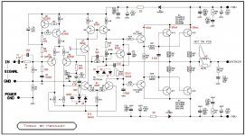
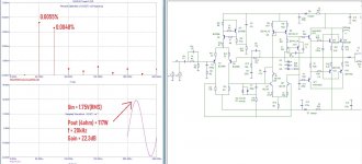
This is the schematic that I built my first design experimentation that actually worked in a real hardware. I was reminded by this design when I saw your posting. If time permits I may have to try your mods and see if it will fit in my schematic as I wanted to modify this (and perhaps see more progress 😉).
The 33pf caps attached at the base to collector junction of the drivers was not included in my actual build. It was drawn in the schematic as a preventive measure in case the amp will oscillate wildly (they are of no help in the actual build). What stopped the wild oscillation was the cap at the right leg of the VAS.
no argument, just my thought based on actual experimentation and not a technical point of view. The more knowledgeable ones is very much welcome to point it out and give more emphasis on the matter.it's not professional to argue, this capacitance multiplied by the gain of the Q8Q7 cascode equalizes the frequency characteristics of this cascode and the Q9 transistor, otherwise, when a common-mode signal appears, these transistors will be at an ultra-high frequency in one phase.
Henk.
😉
BTW have you seen this schematic? The other design of Dr. Bora with similar scheme for the VAS.
I will say that today, there are very few topological solutions that really sound good, I mean comfortable for hearing. Nearly all progressive correction solutions sound comfortable to the ear because the gain is more linear within the HiFi, up to deep NFB.Henk,
This is the schematic that I built my first design experimentation that actually worked in a real hardware. I was reminded by this design when I saw your posting. If time permits I may have to try your mods and see if it will fit in my schematic as I wanted to modify this (and perhaps see more progress 😉).
It's good that they weren't included. their location is terrible.The 33pf caps attached at the base to collector junction of the drivers was not included in my actual build.
Of course, since we received Miller's correction, which stops not only oscillation but also high-quality sound, the reason is that it simply reduces the gain at high frequencies in the audio range until a deep negative connection is introduced - this is essentially a tone-corrector in the audio range under the influence of a negative feedback.What stopped the wild oscillation was the cap at the right leg of the VAS.
Last edited:
What is unusual about her? the absence of any correction admitted that the gain under negative feedback is very weak, this has nothing to do with the reference. And the fact that Wilson's stable current source really reduces the proportion of even harmonics is no secret at all. And, as usual, a circuit with minor errors - suitable for radio amateurs, not for a reference solution....BTW have you seen this schematic? The other design of Dr. Bora with similar scheme for the VAS.
Another amplifier with a similar compensation scheme is the SymAsym by Mike Bittner. What do you mean by progressive correction?
It is impossible to obtain a high-quality high-linear amplifier without the introduction of deep NFB. however, with an increase in the depth of the NFB with the standard Miller correction (first method) , the dynamic properties of the amplifier deteriorate significantly, since such a correction has a limit on the depth of the negative connection at high frequencies up to 20-30 dB,What do you mean by progressive correction?
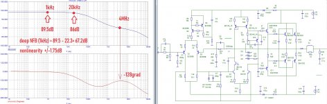
There is a second method that allows you to get around this limitation, this is when the frequency response is reduced with a slope angle of 40 dB / dec, to the left of the phase reversal point, which avoids the instability of the amplifier. However, neither the first nor the second method can significantly improve the quality of the amplifier, since the spectrum of harmonic distortion introduced by transistor amplifiers depends on the quality of the transistors themselves, that is, with an increase in the quality of transistors and their amplification, high-frequency distortion harmonics also grow, with which these methods no longer fully cope.
The third correction method is the dynamic or progressive correction method, which is the use of lead and lag correction circuits to generate a frequency response without variable slope NBF. It is important to strive to ensure that the obtained frequency response does not have points where its slope changes by more than ± 20 dB / dec, this will ensure its uniformity, and as a result, provide good transient response, the possibility of increasing the depth of the NFB in the entire audio frequency band. And as a result, the growth of linearity and the quality of the amplifier. An indispensable condition for the applicability of a progressive amplifier correction method is to increase its gain with an open circuit NBF, in fact, why in all tweaks I reduce the sensitivity of amplifiers to 20-24 dB, this also reduces the level of interference at the amplifier input, and given that modern sources have an output within 1 -2V (RMS), then this is not a problem at all, except for an increase in the quality of sound reproduction.
yes, I know.Another amplifier with a similar compensation scheme is the SymAsym by Mike Bittner.
Last edited:
- Home
- Amplifiers
- Solid State
- "a thread dedicated to our great dr bora"