We have been speaking here about distributed mode of sound waves across the thin flat surface, with a transducer placed at the back at 2/5th, 3/5th distance from the edges to get the best sound. But how come sound/music comes out quite crip and clean with the transducer (exciter) placed at the thinner edge of the sheet/panel? How does the distributed mode of sound waves go from the thinner edge upwards? In a half circle waves? Or ripples? How does the sound come from the flat surface in all directions? Something to ponder about, and experiment on.

70cm x 40 cm x 2cm EPS sheet with 2 transducers placed at 12cm from edge facing up at the thinner (2cm) edge. Sound comes from front, back and in plane and gives stereo effect any place around it.
70cm x 40 cm x 2cm EPS sheet with 2 transducers placed at 12cm from edge facing up at the thinner (2cm) edge. Sound comes from front, back and in plane and gives stereo effect any place around it.
Last edited:

Does this play left channel to one exciter and right to the other?View attachment 1112157
70cm x 40 cm x 2cm EPS sheet with 2 transducers placed at 12cm from edge facing up at the thinner (2cm) edge. Sound comes from front, back and in plane and gives stereo effect any place around it.
Please describe the "stereo effect" as much as you can.
What kind of soundstage do you experience? How wide? How deep? What kind of placement of instruments?
Does the panel hang?
Do you have it supported?
Do the exciters sit on something (e.g., table or floor)?
These kind of nonlinear-thought experiments make this discussion thread very interesting!
Many thanks.
Made my day.
- Andreas
Last edited:
Yes, one exciter plays the left channel, the other the right. The exciters were placed on a glass table, but isolated from it with cloth and soft pads. The exciters have an aluminium cover around the magnet. These were bought a long time ago, just sitting in a drawer. They work without the plate too, just by touching the screwed-in spider.Does this play left channel to one exciter and right to the other?
Please describe the "stereo effect" as much as you can.
What kind of soundstage do you experience? How wide? How deep? What kind of placement of instruments?
Does the panel hang?
Do you have it supported?
Do the exciters sit on something (e.g., table or floor)?
These kind of nonlinear-thought experiments make this discussion thread very interesting!
Many thanks.
Made my day.
- Andreas


I was sitting behind the sheet holding it tightly against the exciters. The she did the same thing and I walked around. It was hard to say which exciter gave which sound. The room was filled with sort of 3-d sound. My wife could place which instrument was playing and where the player was situated in front of her, while standing walking about 1.5 m in front of the sheet.
The idea is the fix the exciters onto a frame, and the sheet to the frame, and then hang it on the wall to see how it sounds, but that has to wait till late spring. It's too cold and windy to work outside. If you guys have a place to tinker and why not try this out?
I've been pondering over how the sound moved through the sheet from the thinner side and came out of the very much wider side and how, why it became so amplified and crisp. There must be a scientific thought behind this. Well, I left the tech Uni some four decades ago, so these experiments and thinking keeps my grey cells activated. 🙂 Not that I need a new pair of speakers. I write here hoping some (younger) chaps would catch the bug and continue to experiment.
chdsl: "I write here hoping some (younger) chaps would catch the bug and continue to experiment."
I have two pair of exciters on the way, definitely gonna' try this method out. Thanks
I have two pair of exciters on the way, definitely gonna' try this method out. Thanks
Hello Chdsl,Yes, one exciter plays the left channel, the other the right. The exciters were placed on a glass table, but isolated from it with cloth and soft pads. The exciters have an aluminium cover around the magnet. These were bought a long time ago, just sitting in a drawer. They work without the plate too, just by touching the screwed-in spider.
View attachment 1112261 View attachment 1112262
I was sitting behind the sheet holding it tightly against the exciters. The she did the same thing and I walked around. It was hard to say which exciter gave which sound. The room was filled with sort of 3-d sound. My wife could place which instrument was playing and where the player was situated in front of her, while standing walking about 1.5 m in front of the sheet.
The idea is the fix the exciters onto a frame, and the sheet to the frame, and then hang it on the wall to see how it sounds, but that has to wait till late spring. It's too cold and windy to work outside. If you guys have a place to tinker and why not try this out?
I've been pondering over how the sound moved through the sheet from the thinner side and came out of the very much wider side and how, why it became so amplified and crisp. There must be a scientific thought behind this. Well, I left the tech Uni some four decades ago, so these experiments and thinking keeps my grey cells activated. 🙂 Not that I need a new pair of speakers. I write here hoping some (younger) chaps would catch the bug and continue to experiment.
I agree that all this stuff around DML keeps the brain activity... seems also we were at school in the same period!
Some explanations from a specialist of vibration in solid might help. Somebody?
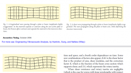
What I can bring in the topic is among the reading I had this one : STRUCTURAL ACOUSTICS TUTORIAL—PART 1: VIBRATIONS IN STRUCTURES by Stephen Hambric shows different modes of progations in a plate (see extract below). DML with exciter on the rear is based on the bending waves (fig 3). Your experiment looks like being in longitudinal waves (fig 1). Don't ask me more...
If true, a big difference would be (according to the drawing) front and rear waves are in phase in your experiment where they are out of phase in bending waves.
Perhaps without any measurements, it would be interesting to have an estimation of the efficiency (the level for a given volume at the amp), the response (bass, treble), the smoothness of the FR in comparison to a DML with the same membrane, same exciter.
With measurements, in addition of the FR, I would check the phase... unfortunatly my do(wish)list is already too long!
Christian
Attachments
@homeswinghome
My experiments with the vertical sheet started after seeing the video on Ammos speaker, and then finding the vids on Sony glass (plastic) tube. Two ideas on trying to get the omnidirectional sound effect. Both Ammos and Sony were trying to get only the high frequency from upfiring (tiny ?) actuators. Ammos had a plane sheet, Sony a tube. Only the tube is the stiffest structure of the two. It is supposed to have 3 actuators. I am trying to fathom how the tube is transferring the sound outwards from its surface. The Sony's tube is closed at the top. The articles on these gadgets generally use the word actuator, but maybe they are using piezoelectric speakers. Anyway, a lot to ponder about.
My experiments with the vertical sheet started after seeing the video on Ammos speaker, and then finding the vids on Sony glass (plastic) tube. Two ideas on trying to get the omnidirectional sound effect. Both Ammos and Sony were trying to get only the high frequency from upfiring (tiny ?) actuators. Ammos had a plane sheet, Sony a tube. Only the tube is the stiffest structure of the two. It is supposed to have 3 actuators. I am trying to fathom how the tube is transferring the sound outwards from its surface. The Sony's tube is closed at the top. The articles on these gadgets generally use the word actuator, but maybe they are using piezoelectric speakers. Anyway, a lot to ponder about.
@pway
Hello Paul,
Here is a tentative of placing EPS in the material graph.
It is based on the following assumption :
From that, the candidates might be :
At this step, I think the chart is a good tool helping to see where is a material according to different criteria and targets.
The next steps might be to choose the EPS according to it, measure the density and the Young Modulus (tap test), place it in the chart, adjust the thickness for the compromise coincidence frequency / bandwidth.
Christian

Hello Paul,
Here is a tentative of placing EPS in the material graph.
It is based on the following assumption :
- EPS 15kg/m³, E = 5MPa. Fits with my experience
- EPS 30kg/m³, E = 15Mpa. Large dispersion of values here on the web. No sample at hand.
- linear interpolation between those values (see previous post) E = 2.rho/3 -5 rho in kg/m³, E in MPa
- 15, 20, 25, 30kg/m³ EPS
- in 5, 10, 15, 20mm thickness
- the targeted areas proposed in my previous paper (blue for home audio, blue for PA)
From that, the candidates might be :
- for home application : 25 or 30kg/m³, 15mm is too thick according to the criteria, 12mm?
- for PA : 20kg/m³ in 20mm or even 25kg/m³ in 20mm.
At this step, I think the chart is a good tool helping to see where is a material according to different criteria and targets.
The next steps might be to choose the EPS according to it, measure the density and the Young Modulus (tap test), place it in the chart, adjust the thickness for the compromise coincidence frequency / bandwidth.
Christian
ChristianHello Chdsl,
I agree that all this stuff around DML keeps the brain activity... seems also we were at school in the same period!
Some explanations from a specialist of vibration in solid might help. Somebody?
What I can bring in the topic is among the reading I had this one : STRUCTURAL ACOUSTICS TUTORIAL—PART 1: VIBRATIONS IN STRUCTURES by Stephen Hambric shows different modes of progations in a plate (see extract below). DML with exciter on the rear is based on the bending waves (fig 3). Your experiment looks like being in longitudinal waves (fig 1). Don't ask me more...
If true, a big difference would be (according to the drawing) front and rear waves are in phase in your experiment where they are out of phase in bending waves.
Perhaps without any measurements, it would be interesting to have an estimation of the efficiency (the level for a given volume at the amp), the response (bass, treble), the smoothness of the FR in comparison to a DML with the same membrane, same exciter.
With measurements, in addition of the FR, I would check the phase... unfortunatly my do(wish)list is already too long!
Christian
View attachment 1112304
I would bet that bending waves are still what’s happening here, in spite of the orientation of the exciters.
Chdsl
Try pressing the exciters to the face of the plate in the same area (bottom edge of the plate). I suspect the result may be very similar, just louder (probably).
Eric
Christian@pway
Hello Paul,
Here is a tentative of placing EPS in the material graph.
It is based on the following assumption :
The chart shows :
- EPS 15kg/m³, E = 5MPa. Fits with my experience
- EPS 30kg/m³, E = 15Mpa. Large dispersion of values here on the web. No sample at hand.
- linear interpolation between those values (see previous post) E = 2.rho/3 -5 rho in kg/m³, E in MPa
Note that in the reality, the membrane with be a little bit heavier (a little on the left), stiffer (more to the top) with PVA coating or other coating (mainly stiffer).
- 15, 20, 25, 30kg/m³ EPS
- in 5, 10, 15, 20mm thickness
- the targeted areas proposed in my previous paper (blue for home audio, blue for PA)
From that, the candidates might be :
As a reference, I added the 25kg/m³, 25mm point (Neopor? see Leob PA panels)
- for home application : 25 or 30kg/m³, 15mm is too thick according to the criteria, 12mm?
- for PA : 20kg/m³ in 20mm or even 25kg/m³ in 20mm.
At this step, I think the chart is a good tool helping to see where is a material according to different criteria and targets.
The next steps might be to choose the EPS according to it, measure the density and the Young Modulus (tap test), place it in the chart, adjust the thickness for the compromise coincidence frequency / bandwidth.
Christian
View attachment 1112452
A very rough approximation is that the elastic modulus of a foam scales in proportion to its density squared.
It’s a better approximation for open cell foams than closed cell. But it gives a decent first approximation if you don’t have any real data.
Eric
Hello Eric,Christian
A very rough approximation is that the elastic modulus of a foam scales in proportion to its density squared.
It’s a better approximation for open cell foams than closed cell. But it gives a decent first approximation if you don’t have any real data.
Eric
Do you have a suggestion for a better approximation for EPS than my basic linear heuristic? I haven't found so much data...
Christian
@VelericHello Eric,
Do you have a suggestion for a better approximation for EPS than my basic linear heuristic? I haven't found so much data...
Christian
Hello again Eric
I have searched a bit more and find the Gibson Ashby equation (model?). I think it is what you refer. Applied to EPS, the shape is almost a straight line in the paper I found. OK this not a deep research but seems the graph for EPS point to a quasi straight line. More than the shape of curve (there is an agreement to say E increase according rho), it is the different values of E for a same density which is surprising. I wonder if all of us buying EPS of the same density, ie 20kg/m³ in our different countries we'll find a high dispersion of E or is it a problem in the way to measure E (this is in one paper)?
I think I mentioned this before. On the face of the sheet, the sound is hollow, like coming from a tube/horn. The placing has to be more or less at the 2/5th, 3/5th place, any other place the sound is quite bad. But placing the transducer on the thinner side the sound was quite nice and could be placed at the middle. But with both transducers placed at ~12cm from opposite ends, stereo effect is achieved. Best try this yourself. It'd be nice to hear your subjective feeling on sound effects. I won't be able to do any more testing until the weekend.Christian
I would bet that bending waves are still what’s happening here, in spite of the orientation of the exciters.
Chdsl
Try pressing the exciters to the face of the plate in the same area (bottom edge of the plate). I suspect the result may be very similar, just louder (probably).
Eric
Last edited:
Hi Christian@pway
Hello Paul,
Here is a tentative of placing EPS in the material graph.
It is based on the following assumption :
The chart shows :
- EPS 15kg/m³, E = 5MPa. Fits with my experience
- EPS 30kg/m³, E = 15Mpa. Large dispersion of values here on the web. No sample at hand.
- linear interpolation between those values (see previous post) E = 2.rho/3 -5 rho in kg/m³, E in MPa
Note that in the reality, the membrane with be a little bit heavier (a little on the left), stiffer (more to the top) with PVA coating or other coating (mainly stiffer).
- 15, 20, 25, 30kg/m³ EPS
- in 5, 10, 15, 20mm thickness
- the targeted areas proposed in my previous paper (blue for home audio, blue for PA)
From that, the candidates might be :
As a reference, I added the 25kg/m³, 25mm point (Neopor? see Leob PA panels)
- for home application : 25 or 30kg/m³, 15mm is too thick according to the criteria, 12mm?
- for PA : 20kg/m³ in 20mm or even 25kg/m³ in 20mm.
At this step, I think the chart is a good tool helping to see where is a material according to different criteria and targets.
The next steps might be to choose the EPS according to it, measure the density and the Young Modulus (tap test), place it in the chart, adjust the thickness for the compromise coincidence frequency / bandwidth.
Christian
View attachment 1112452
Im back temporarily from our holiday trip up the coast, had to bring back our dog to have a tooth removed 🙁 Driving back tomorrow (~340km) I haven't followed the argument about the B to mu^x ratios, so I can't offer any opinion atm. In the end I ordered some 15mm sheets, some 20mm, and a couple of 40mm to experiment with milling profiles.
That edge-on excitation reported by chdsl is an interesting development. Foam is unusual stuff, relatively easily compressible but with Poisson ~0.3 for small stresses. Could it be that longitudinal waves have been observed, and the higher speed is giving better efficiency? I would not have expected much output though from longitudinal waves.
I think those who created the exciter for the flat panel, did so that the voice coil be flat as possible, its diameter is much wider than the voice coil of a normal cone speaker. The area touched by this kind of an exciter is bigger than, say of a dismantled cone speaker.
When touching the thinner edge of the sheet, the exciter I used actually transferred the vibration to the small plate through a small screw, then to a bit wider head, then to the plate. The screw diameter is 4mm, the head, 8mm and the plate 32mm, the plate itself being a small speaker. Even the fixed by tiny screws 'frog legs' acted as tiny sound speaker. The thing is the 4mm screw is the main element of transferring the voice coil vibrations to anything outside it. It didn't really change the sound coming from the 20mm thin EPS sheet edge, whether I kept it tight on the middle of the 32mm plate, or its edge.

Here's an idea to check on; if you have another type of an exciter, just paste a screw, thinnest possible, head down on the middle of the exciter, push the other end into the thin edge of the EPS sheet, or any sheet you have, check the sound it gives. The exciter must be fixed to some surface, or held unmoving by its own weight, and the sheet must be held tightly, or fixed to a frame. I won't be able to do these experiments until the weekend, maybe some of you can. 🙂
When touching the thinner edge of the sheet, the exciter I used actually transferred the vibration to the small plate through a small screw, then to a bit wider head, then to the plate. The screw diameter is 4mm, the head, 8mm and the plate 32mm, the plate itself being a small speaker. Even the fixed by tiny screws 'frog legs' acted as tiny sound speaker. The thing is the 4mm screw is the main element of transferring the voice coil vibrations to anything outside it. It didn't really change the sound coming from the 20mm thin EPS sheet edge, whether I kept it tight on the middle of the 32mm plate, or its edge.
Here's an idea to check on; if you have another type of an exciter, just paste a screw, thinnest possible, head down on the middle of the exciter, push the other end into the thin edge of the EPS sheet, or any sheet you have, check the sound it gives. The exciter must be fixed to some surface, or held unmoving by its own weight, and the sheet must be held tightly, or fixed to a frame. I won't be able to do these experiments until the weekend, maybe some of you can. 🙂
Paul, I think you are correct not to expect much output from longitudinal waves.That edge-on excitation reported by chdsl is an interesting development. Foam is unusual stuff, relatively easily compressible but with Poisson ~0.3 for small stresses. Could it be that longitudinal waves have been observed, and the higher speed is giving better efficiency? I would not have expected much output though from longitudinal waves.
The lateral deflection from compression/tension in longitudinal wave scales as 1/E, while lateral deflections from bending waves scale as (L/t)^3/E, where L is the plate length or width, and t is the plate thickness. So as soon as the plate length or width is 10 times its thickness, bending wave deflections will be on the order of 1000 times greater than deflections due to longitudinal waves.
So even if the exciter is oriented on the edge like Chdsl has done, there will be some component of the force that will end up being perpendicular to the plane of the panel, and which results in flexural waves.
The Hambric link Christian shared notes that most radiated sound from plates etc comes from flexural waves. It's entertaining to think that we have found an exception, but I find it highly unlikely.
Eric
Hello chdsl,
I would look at this for making a tube speaker https://www.amazon.com/Ultra-Thin-Wall-Round-Tubes-PRT07040/dp/B07QZBHSH8?ref_=ast_sto_dp&th=1
You can use the end cap to secure the tube to the exciter.
Cheers.
I would look at this for making a tube speaker https://www.amazon.com/Ultra-Thin-Wall-Round-Tubes-PRT07040/dp/B07QZBHSH8?ref_=ast_sto_dp&th=1
You can use the end cap to secure the tube to the exciter.
Cheers.
I can use an ordinary drinking glass to experiment with, just holding the exciter flat on the edge, even two of them. By the way, you guys can too.Hello chdsl,
I would look at this for making a tube speaker https://www.amazon.com/Ultra-Thin-Wall-Round-Tubes-PRT07040/dp/B07QZBHSH8?ref_=ast_sto_dp&th=1
You can use the end cap to secure the tube to the exciter.
Cheers.

Thanks for the link. Just imagine having a thin long tube fixed over an exciter's plate giving you the music, the bottom part with the exciter hidden inside an ornamental tube or box, or in a vase, and even with some led lights in it. I'm somewhat restricted till the weekend. Why not try this yourself?
Hello PaulHi Christian
Im back temporarily from our holiday trip up the coast, had to bring back our dog to have a tooth removed 🙁 Driving back tomorrow (~340km) I haven't followed the argument about the B to mu^x ratios, so I can't offer any opinion atm. In the end I ordered some 15mm sheets, some 20mm, and a couple of 40mm to experiment with milling profiles.
That edge-on excitation reported by chdsl is an interesting development. Foam is unusual stuff, relatively easily compressible but with Poisson ~0.3 for small stresses. Could it be that longitudinal waves have been observed, and the higher speed is giving better efficiency? I would not have expected much output though from longitudinal waves.
Have a good trip, enjoy the remaining days on the coast!
If you could inform us about plates density and Young modulus (see the tap test method), it would be really great to progress in the calculation approach.
Christian
Thanks Tagis. good proposal. I think I have this kind of tube in my workshop. Even if those new ideas create "forks" in the stream of my ideas, I am curious of practical results. Let see what will be possible at the WE.Hello chdsl,
I would look at this for making a tube speaker https://www.amazon.com/Ultra-Thin-Wall-Round-Tubes-PRT07040/dp/B07QZBHSH8?ref_=ast_sto_dp&th=1
You can use the end cap to secure the tube to the exciter.
Cheers.
Christian
This might work with plastic tubes, plexi-glass tubes, lamp shades, timber tubes, vases, glasses etc, etc. Maybe the tube doesn't have to be even straight.Thanks Tagis. good proposal. I think I have this kind of tube in my workshop. Even if those new ideas create "forks" in the stream of my ideas, I am curious of practical results. Let see what will be possible at the WE.
Christian
- Home
- Loudspeakers
- Full Range
- A Study of DMLs as a Full Range Speaker