Thank you Burnt. By the way, do not hesitate for any kind of error correction, including English! The bibliography is in the last page after the lines of code.Hi Christian,
I read this over the weekend. Its a great paper, well done. Much food for thought.
Burnt.

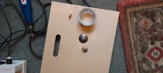
Steve, if you don't mind,I forgot I had this panel and a cutter, couldn't find the cutter so used the grinder.
Two minute job.
The silver dust cover dome on the panel was from a small cone driver.
Steve.
Please explain why you're using whizzers and domes and dust covers etc to boost certain frequencies. I suspect that such solutions will produce pistonic action and hence beaming and directivity.
What am I missing?
Hi ChristianHello Eucy,
It is a 2mm hole in the center. The way I made them is a bit different from yours. I made test on different samples of material I had : EPS, XPS, plywood, "homemade plywood".
In few words :
The FR were "only" on the axis. No conclusion about a possible effect on the dispersion.
- Very easy to do. As I drilled also a 2mm hole in the panel and the exciter have also a 2mm hole, it was very easy to align them.
- For low density materials (EPS, XPS) there is the boost you mention but the FR stops a bit before then
- For the high density materails (plywood or similar)... The on axis FR was not changed in an obvious way like for the PS.
I have the intention to gather the pictures and the FR to share them. Sorry I put it in a second time compare to the influence of the additional mass those FR show.
Christian
What about listening tests
Have you done any dome on and off vocal tests ?
Eucy
This exciter is considerably deeper than the rest. It is possible that it is underhung design with short coil and long gap. One of the latest designs perhaps. Has anybody cut off the spider and looked at the motor and voice coil?
TEBM35C10-4 has aluminium voice coil, motor strength probably too little for dml.
TEBM46C20N has kapton voice coil, thin 2 layer winding. Stiff and very thin fabric spider. Unbalanced, buzzing, crackling noise when played without surround and cone.
Out of curiosity dissasembled Vifa Ne149, voice coil under the dust cup is too short to be used for dml. With removed cone sounded very bad, strong rocking, rubbing distortion, voice coil unbalanced in the gap.
Aura Sound NS-6 has nice underhung motor but voice coil is too short above spider to be used for dml. Strong rocking distortion when played without cone.
Dayton exciter DAEX30HESF-4 is built more robust. Denser double layer fabric spider, thick kapton voice coil, 4 layer copper winding with thicker wire, more x=max, more motor strength. Very quiet mechanically played on its own.
The quietest motor i have seen so far is from Scan-speak 12mu. It has very soft, compliant, large diameter spider, but when played without cone it has no sound of its own even when changing angles abruptly, with largest x-max I have seen.
Unfortunately one of drivers have manufacturing defect, voice coil is glued in angle to the spider.
Attachments
Whizzer and domes do not produce pistonic motion and beaming , they already exist in the exciter area.Steve, if you don't mind,
Please explain why you're using whizzers and domes and dust covers etc to boost certain frequencies. I suspect that such solutions will produce pistonic action and hence beaming and directivity.
What am I missing?
I mainly use my soft fabric dome to try and prevent the problems that I have mentioned in the exciter area before.
But not to boost frequencies.
But if it also helps the sound a little I am very grateful.
This does not work with all panel types.
Many years ago I noticed that DML is not 100% DML.
DML has pistonic action in the exciter area which produces bendingwaves, these bendingwaves reflecting back from the edges causing distributed modes.
How much pistonic action that is in the exciter area depends on the flexibility of the panel and lightness , and size.
One of the problems levelled at DML is that the sound on some panels is coming from behind.
There are ways to get over this problem and a whizzer is one method.
On eps I used to thin the material in front of the exciter.
On ply I used thin strips of paper.
I don't usually use whizzers , but I must admit that this morning I did play around with some and will post some pics and measurements after doing some more testing.
If a panel is lacking some top end for some reason , something like a whizzer can help ,it can also help the midrange a little as well if done well.
I think my best sounding panels sound so good because I encourage pistonic action ?
Even shelley katz of podium fame believes DML should be used with pistonic drivers for best performance.
I hope this has answered your question ?
Steve.
Hi lenta,
Thank you for these images and the references, there is a lot of useful information here. I have managed to find the website designer of some of the Tectonic exciters http://www.grahamlandick.com/ and one of his patents is full of information on his approach which is very inventive. https://uspto.report/patent/app/20190261092
I wonder if Mr Landick posts on here, quite a few professionals do.
Burnt
Thank you for patents. I have seen his homepage and his posts somewhere in forums about dml. His latest design is Dayton Audio DAEX30HESF-4 called Production Radial 'Tulip' Exciter. It is most probably similar to Aura NRT underhung design. Still the best exciter readily available.Can you please make a drawing of your idea?Interesting discussion about the possibility of DIY exciters. I raised this some time ago on the forum too.
I think it's probably very difficult to build a better exciter by competing in terms of manufacturing techniques. However there may be some low-hanging fruit stemming from the fact that we don't have to build a saleable exciter product, but a complete system.
For example, exciters have to compromise on field strength because one side of the exciter has to be open, with resulting field leakage. But we have a good deal of flexibility in the geometry of the panel, and are not limited by size because we can separate the moving parts from the heavy parts carrying the magnetic flux. You could, for example, put a hole through the panel, glue the coil & former inside that, and pass a soft iron core clear through the hole, with neodymium magnets on both sides. Of course it does need to be supported on both sides, but the higher field strength & better geometry should mean that the tolerances are less important. Maybe you could also think about eliminating the coil wiring altogether by using induction coils, at least for low frequency.
Lenta.
Finally found it on sound imports.
But not on the tectonic site?
https://www.soundimports.eu/en/tectonic-elements-tebm54c30-8.html
Steve.
Finally found it on sound imports.
But not on the tectonic site?
https://www.soundimports.eu/en/tectonic-elements-tebm54c30-8.html
Steve.
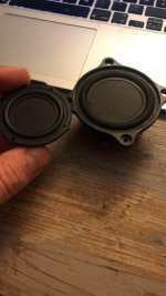
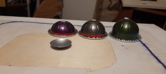
I just took some measurements of using different size coffee whizzers 😃
The coffee whizzers were in 4 sizes .
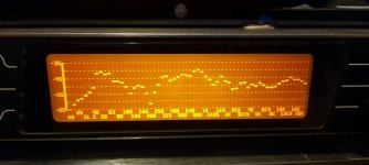
Pic 2 is the largest, far to deep.
Pic 3 was the smallest still not very good ?
Pic4 was without any whizzer.
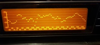
Pic5 was the smallest of the uncut coffee whizzers on the left in pic 1.
This whizzer increased the output in the 1k to 10k area, and sounds good,so far , more listening needed.
The three sizes were 2cm, 2.5cm and 3cm.
I didn't bother showing the 2.5cm measurement ,as it too was not good enough either.
This panel by the way, was the crate ply on a canvas panel.
I did try it on the crate ply , but that panel already had plenty of HF and had a pretty flat response.
So was hard to compare.
The canvas is probably over damping the crate ply ,so a little boost from the coffee whizzer seems to work quite well.
The whizzer Gives the panel a little more sparkle and life.
I will have to pop around to my friends house and have another cup of his lovely coffee ☕️
I wonder what he will say when he asks me what coffee I would like, and I say , a 2cm please 🤣
Steve.
The coffee whizzers were in 4 sizes .
Pic 2 is the largest, far to deep.
Pic 3 was the smallest still not very good ?
Pic4 was without any whizzer.
Pic5 was the smallest of the uncut coffee whizzers on the left in pic 1.
This whizzer increased the output in the 1k to 10k area, and sounds good,so far , more listening needed.
The three sizes were 2cm, 2.5cm and 3cm.
I didn't bother showing the 2.5cm measurement ,as it too was not good enough either.
This panel by the way, was the crate ply on a canvas panel.
I did try it on the crate ply , but that panel already had plenty of HF and had a pretty flat response.
So was hard to compare.
The canvas is probably over damping the crate ply ,so a little boost from the coffee whizzer seems to work quite well.
The whizzer Gives the panel a little more sparkle and life.
I will have to pop around to my friends house and have another cup of his lovely coffee ☕️
I wonder what he will say when he asks me what coffee I would like, and I say , a 2cm please 🤣
Steve.
Attachments


The coffee whizzers were only held on with bluetack.
I just remembered that I did try to glue one of these coffee whizzers onto one of these panels with pva some time ago, but it just fell off when I tried to play music.
Steve.
I just remembered that I did try to glue one of these coffee whizzers onto one of these panels with pva some time ago, but it just fell off when I tried to play music.
Steve.
Actually, now you've forced me to think about it, I realise the idea won't work. I was thinking of a bar magnet with a solenoid around it. But forces on bar magnets only occur because the magnet has ends, which are attracted or repelled by the N or S ends of a solenoid. Once completely immersed in a uniform field, there is no resultant force on the bar magnet.Can you please make a drawing of your idea?
I've actually been working on this. There are many significant advantages.You could, for example, put a hole through the panel, glue the coil & former inside that, and pass a soft iron core clear through the hole, with neodymium magnets on both sides. Of course it does need to be supported on both sides, but the higher field strength & better geometry should mean that the tolerances are less important. Maybe you could also think about eliminating the coil wiring altogether by using induction coils, at least for low frequency.
But the problem is the alignment of the VC onto the core, and keeping it aligned under rough handling.
The attached pdf describes one variation of the coil-within-the-panel concept, and the design keeps the VC and magnet assembly nicely aligned.Interesting discussion about the possibility of DIY exciters. I raised this some time ago on the forum too.
I think it's probably very difficult to build a better exciter by competing in terms of manufacturing techniques. However there may be some low-hanging fruit stemming from the fact that we don't have to build a saleable exciter product, but a complete system.
For example, exciters have to compromise on field strength because one side of the exciter has to be open, with resulting field leakage. But we have a good deal of flexibility in the geometry of the panel, and are not limited by size because we can separate the moving parts from the heavy parts carrying the magnetic flux. You could, for example, put a hole through the panel, glue the coil & former inside that, and pass a soft iron core clear through the hole, with neodymium magnets on both sides. Of course it does need to be supported on both sides, but the higher field strength & better geometry should mean that the tolerances are less important. Maybe you could also think about eliminating the coil wiring altogether by using induction coils, at least for low frequency.
However, the shortcoming is that the VC does not sit within a pole gap: There's a core magnet, but there's no surrounding pole for the VC to cut the magnetic field.
The BL would therefore probably be a lot less than half of what it could or should be.
Attachments
Last edited:
Hi Eucy,Hi Christian
What about listening tests
Have you done any dome on and off vocal tests ?
Eucy
No vocal tests on a working panel. It was measurements on small piece of test panels
Radial ThoughtsI've actually been working on this. There are many significant advantages.
But the problem is the alignment of the VC onto the core, and keeping it aligned under rough handling.
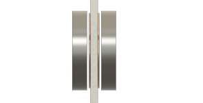
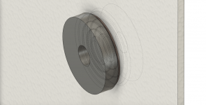
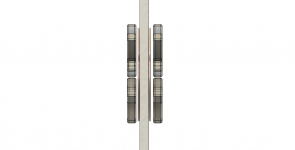
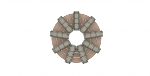
@Andre Bellwood, I had some thoughts in the same direction, mounting coils directly on the panels, but I came out in a different place. You can use flat coils mounted directly to the surface if you use radially magnetised ring magnets. To max out the field strength you can use two sets of coils and magnets on opposite sides which would flatten and intensify the magnetic field. You would have to invert the phase on one set of coils obvs. A manufacturer would be able to get custom ring magnets made up which is too expensive for DIY but you can sort off simulate the same effect using a radial array of bar magnets. Images attached.
I thought there were a number of benefits in that you can split the flat coils into several concentric coils allowing you to control inductance by summing in parallel/series to get the inductance you need which might help the top end performance. Coil heating would also be reduced as the coils are in open air and free to radiate and conduct away heat helping to extend performance limits. As my preference would be to use neodymium magnets there is also the benefit of getting iron out of the circuit reducing eddy current effects, although I am not sure if this is significant. Robustness and alignment tolerance will be much better as the displacement of coil to magnets by a few millimetre is no long a disaster, just a mild drop in performance.
One of the interesting questions for me is how you would treat the voice coil mass now it is directly attached to the panels and the effect this has on mechanical impedance and impulse transmission. This is all very theoretical at the moment, and predicated on being able to get a high enough B. Increasing L will be trivial. I expect there is something I have not thought of that will kill the idea, there usually is, but if I get anywhere I will report back to the group.
Burnt
Attachments
It solves the problem of no net force by having a two magnets with the same poles facing outwards. But I think it would be quite non-linear because it's depending on the interaction of the edges of the magnetic field of the magnet and (because the coil is short) also the edges of the solenoid field as well. And also, as you say, lots of field leakage.The attached pdf describes one variation of the coil-within-the-panel concept, and the design keeps the VC and magnet assembly nicely aligned.
However, the shortcoming is that the VC does not sit within a pole gap: There's a core magnet, but there's no surrounding pole for the VC to cut the magnetic field.
The BL would therefore probably be a lot less than half of what it could or should be.
This setup is very similar to fig 5a in the parent Andre just posted.Radial Thoughts
@Andre Bellwood, I had some thoughts in the same direction, mounting coils directly on the panels, but I came out in a different place. You can use flat coils mounted directly to the surface if you use radially magnetised ring magnets. To max out the field strength you can use two sets of coils and magnets on opposite sides which would flatten and intensify the magnetic field. You would have to invert the phase on one set of coils obvs. A manufacturer would be able to get custom ring magnets made up which is too expensive for DIY but you can sort off simulate the same effect using a radial array of bar magnets. Images attached.
I thought there were a number of benefits in that you can split the flat coils into several concentric coils allowing you to control inductance by summing in parallel/series to get the inductance you need which might help the top end performance. Coil heating would also be reduced as the coils are in open air and free to radiate and conduct away heat helping to extend performance limits. As my preference would be to use neodymium magnets there is also the benefit of getting iron out of the circuit reducing eddy current effects, although I am not sure if this is significant. Robustness and alignment tolerance will be much better as the displacement of coil to magnets by a few millimetre is no long a disaster, just a mild drop in performance.
One of the interesting questions for me is how you would treat the voice coil mass now it is directly attached to the panels and the effect this has on mechanical impedance and impulse transmission. This is all very theoretical at the moment, and predicated on being able to get a high enough B. Increasing L will be trivial. I expect there is something I have not thought of that will kill the idea, there usually is, but if I get anywhere I will report back to the group.
Burnt
I did mention some years back , bolting two exciters on opposite sides of my ply panels.
I never managed to get around to doing it, but thought it could be good for pro use.
Steve.
If I understand the design it also suffers from dramatic field leakage, and is even more non-linear because the force increases as the coil approaches the magnet. So it risks colliding.Radial Thoughts
@Andre Bellwood, I had some thoughts in the same direction, mounting coils directly on the panels, but I came out in a different place. You can use flat coils mounted directly to the surface if you use radially magnetised ring magnets. To max out the field strength you can use two sets of coils and magnets on opposite sides which would flatten and intensify the magnetic field. You would have to invert the phase on one set of coils obvs. A manufacturer would be able to get custom ring magnets made up which is too expensive for DIY but you can sort off simulate the same effect using a radial array of bar magnets. Images attached.
I thought there were a number of benefits in that you can split the flat coils into several concentric coils allowing you to control inductance by summing in parallel/series to get the inductance you need which might help the top end performance. Coil heating would also be reduced as the coils are in open air and free to radiate and conduct away heat helping to extend performance limits. As my preference would be to use neodymium magnets there is also the benefit of getting iron out of the circuit reducing eddy current effects, although I am not sure if this is significant. Robustness and alignment tolerance will be much better as the displacement of coil to magnets by a few millimetre is no long a disaster, just a mild drop in performance.
One of the interesting questions for me is how you would treat the voice coil mass now it is directly attached to the panels and the effect this has on mechanical impedance and impulse transmission. This is all very theoretical at the moment, and predicated on being able to get a high enough B. Increasing L will be trivial. I expect there is something I have not thought of that will kill the idea, there usually is, but if I get anywhere I will report back to the group.
Burnt
- Home
- Loudspeakers
- Full Range
- A Study of DMLs as a Full Range Speaker